Large effective area fiber with low bending losses

a technology of optical fibers and effective areas, applied in the field of optical fibers, can solve the problems of reducing the service life of optical fibers, and reducing the service life of optical fibers, and achieve the effect of large effective area and low bending losses

Active Publication Date: 2015-06-16
CORNING INC
View PDF15 Cites 2 Cited by
  • Summary
  • Abstract
  • Description
  • Claims
  • Application Information

AI Technical Summary

Benefits of technology

[0005]This disclosure provides optical fibers having a large effective area (Aeff) and low bending losses. The fibers may include a core region, a cladding region, and a coating. The core region may include a central core region and a surrounding core region. The cladding region may include an inner cladding region with a first refractive index and an outer cladding region with a second refractive index profile. The coating may include a primary coating surrounding the cladding and a secondary coating surrounding the primary coating. The in situ modulus of the primary coating may be lower than the in situ modulus of the secondary coating.
[0017]Optical fibers having one or more of the foregoing attributes may further exhibit low bending losses. The optical fiber may exhibit a microbending loss at a wavelength of 1550 nm, as measured by a wire mesh drum test, of less than 0.4 dB / km, or less than 0.3 dB / km, or less than 0.2 dB / km, or less than 0.1 dB / km at a wavelength of 1550 nm.

Problems solved by technology

High power systems often suffer from non-linear optical effects, including self-phase modulation, four-wave-mixing, cross-phase modulation, and non-linear scattering processes, all of which can cause degradation of signals in high powered systems.
Increasing the effective area of an optical waveguide fiber, however, typically results in an increase in macrobending- and microbending-induced losses, which attenuate signal transmission through a fiber.

Method used


Image

  • Large effective area fiber with low bending losses
  • Large effective area fiber with low bending losses
  • Large effective area fiber with low bending losses

Examples


examples

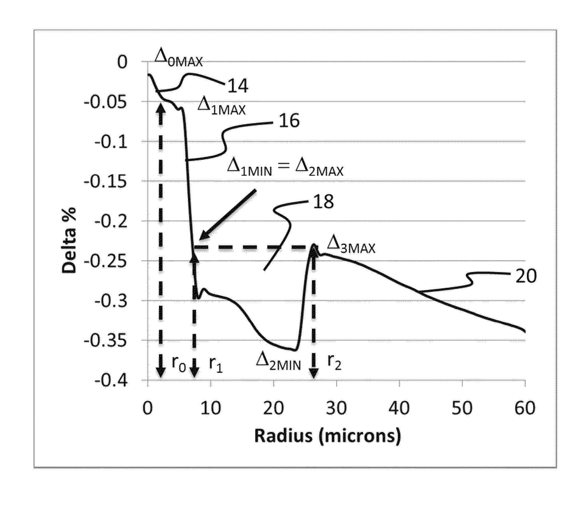
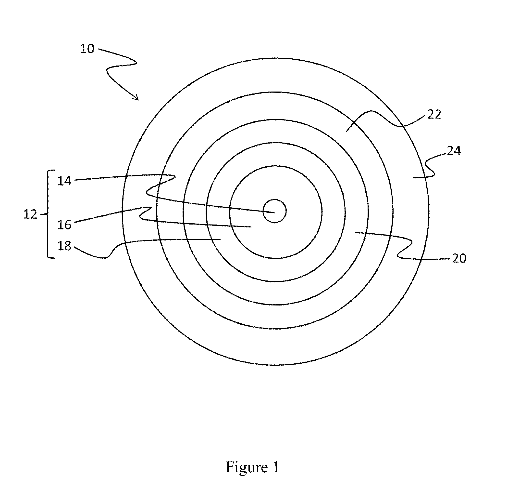
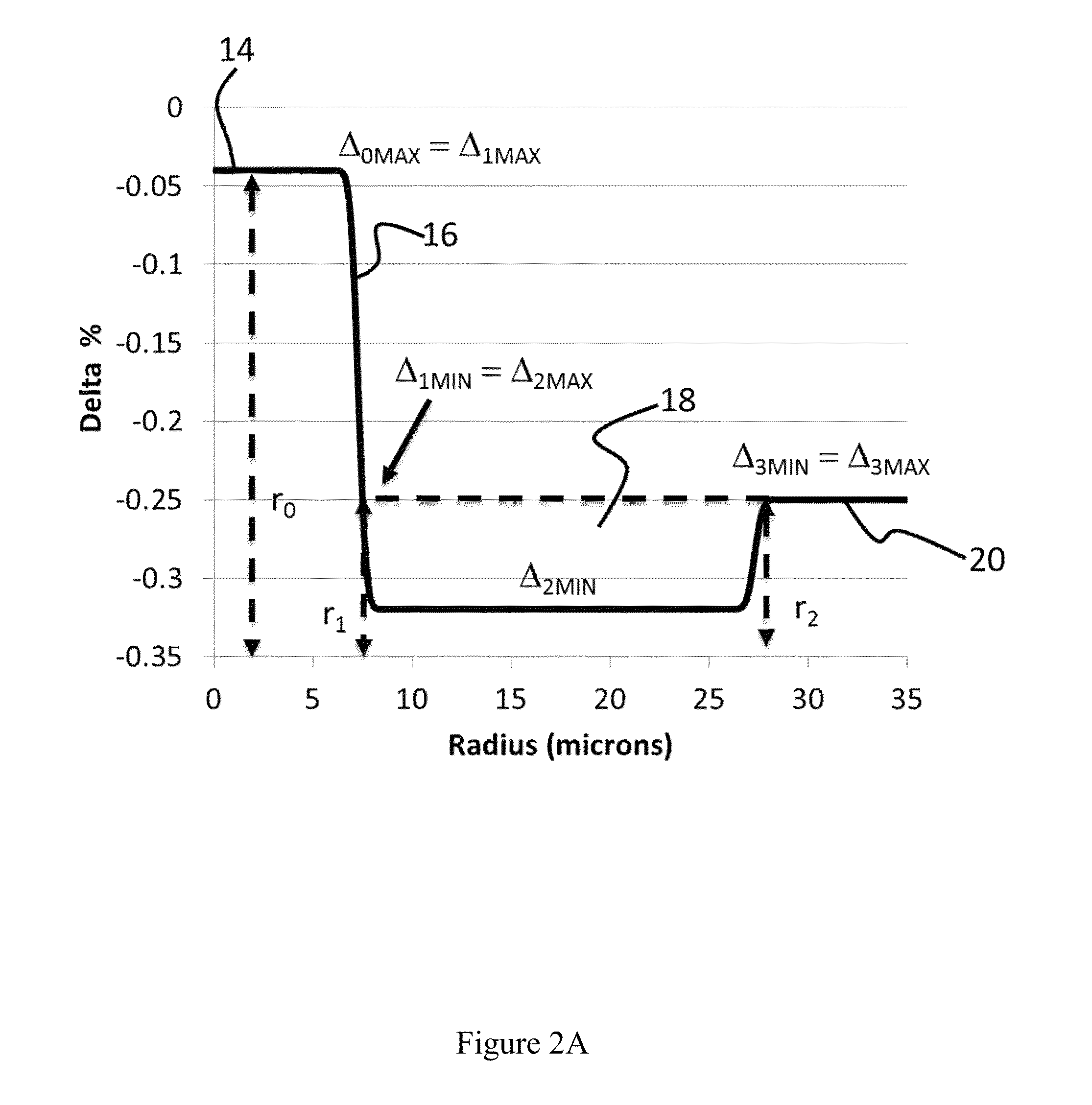
[0125]Representative fibers in accordance with the present disclosure were fabricated and tested to demonstrate selected advantages thereof. The fibers are of the type depicted in FIG. 1 and included a central core region with radius r0 and refractive index percent profile Δ0, a first core region with outer radius r1 and refractive index percent profile Δ1, an inner cladding region with outer radius r2 and refractive index percent profile Δ2, an outer cladding region with outer radius r3 and refractive index percent profile Δ3, a primary coating with outer radius r4, and a secondary coating with outer radius r5.

[0126]The central core region, first core region, inner cladding region and outer cladding region were common to all of the fibers. The refractive index profile across the central core region, first core region, inner cladding region, outer cladding region and radial positions r0, r1, and r2 for one of the fibers is shown in FIG. 3. Each of the fibers had an outer cladding ra...


PUM

PropertyMeasurementUnit
radius r1aaaaaaaaaa
outer diameteraaaaaaaaaa
area Aeffaaaaaaaaaa

Abstract

A fiber having a large effective area at 1550 nm of at least 130 μm2 and a wire mesh drum microbending loss of less than 0.4 dB / km at a wavelength of 1550 nm. The fibers may include a core, a cladding, and a coating. The core may include a central core region and a surrounding first core region. The cladding may include a depressed index inner cladding region and an outer cladding region. The coating may include a primary coating surrounding the cladding and a secondary coating surrounding the primary coating. The primary coating may be formed from a primary composition that may include an acrylate monomer or an N-vinyl amide monomer in combination with an acrylate oligomer, where the acrylate oligomer is present at 35 wt % to 55 wt %. The secondary coating may be formed from a secondary composition including one or more acrylate or diacrylate monomers and an acrylate or methacrylate oligomer, where the oligomer is present at 3 wt % or less.

Description

[0001]This application claims the benefit of priority under 35 U.S.C. §119 of U.S. Provisional Application Ser. No. 61 / 806,005 filed on Mar. 28, 2013 the content of which is relied upon and incorporated herein by reference in its entirety.FIELD[0002]The present disclosure relates generally to optical fibers, and particularly to optical fibers with large effective area and low microbending losses.TECHNICAL BACKGROUND[0003]Optical amplifier technology and wavelength division multiplexing techniques are typically required in telecommunication systems that provide high power transmissions for long distances. The definition of high power and long distances is meaningful only in the context of a particular telecommunication system in which a bit rate, a bit error rate, a multiplexing scheme, and perhaps optical amplifiers are specified. There are additional factors, known to those skilled in the art, which have impacted upon the definition of high power and long distance. However, for mos...

Claims


Application Information

Patent Timeline
Patent Type & Authority Patents(United States)
IPC IPC(8): G02B6/02G02B6/36G02B6/036
CPCG02B6/02019G02B6/02395G02B6/03627G02B6/0281
Inventor BICKHAM, SCOTT ROBERTSONMISHRA, SNIGDHARAJ KUMAROCAMPO, MANUELAPATTERSON, JOAN DIANA
Owner CORNING INC
Why Eureka
Try Eureka