Short pulse lasers using large mode area fibers and higher order modes

Active Publication Date: 2007-06-05
FURAKAWA ELECTRIC NORTH AMERICA INC
View PDF4 Cites 38 Cited by
  • Summary
  • Abstract
  • Description
  • Claims
  • Application Information

AI Technical Summary

Problems solved by technology

However, one of the difficulties associated with femtoseconds pulses in fibers is amplifying the pulses to high power levels.
However, the pulse

Method used


Image

  • Short pulse lasers using large mode area fibers and higher order modes
  • Short pulse lasers using large mode area fibers and higher order modes
  • Short pulse lasers using large mode area fibers and higher order modes

Examples


Embodiment Construction

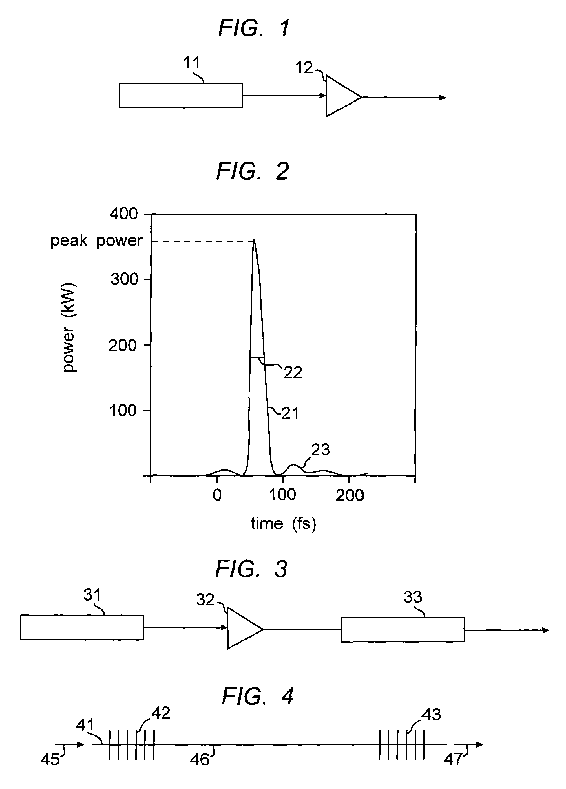
[0023]We have recently demonstrated an erbium amplifier for amplifying femtosecond pulses from a femtosecond fiber laser at 1580 nm. This is described in U.S. patent application Ser. No. 11 / 105,850, filed Apr. 4, 2005, which is incorporated herein by reference. The amplifier works on the principle of self-similar propagation, and the output of the amplifier are pulses that are highly stretched, and have nearly linear chirp. A schematic of the amplifier is shown in FIG. 1, where the output of laser 11 is directed through the fiber amplifier 12. For the purposes of this work, the pulse quality, Q, is defined as the ratio of the energy in the central (strongest) pulse to the energy contained in the entire pulse, including any pedestal or satellite pulses. An illustration of these definitions is shown in FIG. 2. The main pulse body is shown at 21, and the pedestal pulses at 23. The full-width half maximum point is shown at 22. An ideal pulse would have a Q of 1. A high Q is an important...


PUM


Abstract

The specification describes an optical fiber device for propagating and recompressing high energy, ultrashort pulses with minimal distortions due to nonlinearity. The device is based on propagation in a higher order mode (HOM) of a few-moded fiber. Coupling into the HOM may be accomplished using long-period gratings. Features of the HOM fiber mode that are useful for high quality pulse compression include large effective area, high dispersion and low dispersion slope. In a preferred case the long period gratings go through a turn-around point (TAP) at the wavelength of operation.

Description

FIELD OF THE INVENTION[0001]This invention relates to optical fiber devices, such as lasers and amplifiers, that produce high power levels through the use of large effective mode area. More specifically, the devices derive improved performance characteristics when the fiber device is deliberately operated in a higher order mode.BACKGROUND OF THE INVENTION[0002](Parts of the following section may not be prior art.)[0003]Fiber lasers with high pulse energy, good beam quality and excellent optical characteristics have applications in many fields and industries such as analytical spectroscopy (fluorescence, absorption), illumination, remote sensing and environmental spectroscopy (wind speed, biohazards, ecosystem mapping etc), ranging and targeting (collision avoidance, military applications etc) and scientific instrumentation. Fiber lasers with exceptionally short pulse widths, for example, femtosecond fiber lasers, have special applications in these and other fields.[0004]There has be...

Claims


Application Information

Patent Timeline
IPC IPC(8): G02B6/26G02B6/02H01S3/30H04B10/2507H04B10/2537H04B10/2543H04B10/2581
CPCG02B6/02019G02B6/02023G02B6/02266G02B6/03633H01S3/0057H01S3/06725
Inventor RAMACHANDRAN, SIDDHARTHNICHOLSON, JEFFREY
Owner FURAKAWA ELECTRIC NORTH AMERICA INC
Why Eureka
Try Eureka