Radio frequency Langmuir probe

a technology of radio frequency and probe, applied in the field oflangmuir probe, can solve the problems of inability to use the probe as described, system is tuned to operate, and distorted i-v characteristic with associated errors in inferred plasma characteristics, etc., to achieve the effect of reducing rf distortion and low current rating

Inactive Publication Date: 2006-03-21
LAM RES CORP
View PDF6 Cites 123 Cited by
  • Summary
  • Abstract
  • Description
  • Claims
  • Application Information

AI Technical Summary

Benefits of technology

[0020]This invention provides several advantages over the existing known methods. Firstly, the voltage between the plasma and the probe will be low over a wide frequency range so that the probe can be used for multiple frequencies without relying on the designed series filter resonance. Secondly, the probe can be used in systems that employ multiple frequencies without the necessity of designing networks with multiple resonant points. Thirdly, there is no requirement to rely on a tuned filter to reduce RF distortion. The low current rating of some of these tuned filters is thus avoided.

Problems solved by technology

Using a simple Langmuir probe in an RF plasma results in a distorted I-V characteristic with associated errors in the inferred plasma characteristics.
One disadvantage of the tuned probe systems as described is that the system is tuned to operate at a particular frequency, namely the RF plasma driving frequency.
Also, many RF plasma now utilise dual frequency RF power, so that the probe as described cannot be used, since the resonance point of the filter is tuned only to a single frequency.
Another disadvantage is the difficulty in designing and optimising the tuned filter.
One known disadvantage of this system is that the inductor has a low current rating thereby limiting the operating plasma density.

Method used


Image

  • Radio frequency Langmuir probe
  • Radio frequency Langmuir probe
  • Radio frequency Langmuir probe

Examples


Embodiment Construction

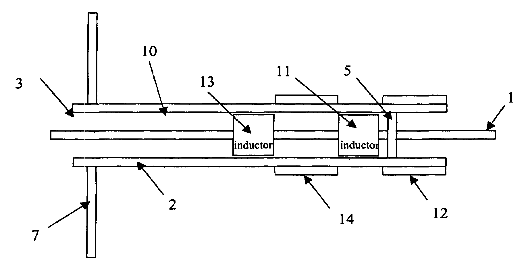
[0029]Referring to FIG. 3, the conductor 10 with probe tip 1 and outer end 3, the surrounding dielectric tube 2 and vacuum seal 5 are all as before. In the present embodiment, however, an RF voltage divider is connected in series between the tip 1 and outer end 3 of the conductor 10. The RF voltage divider comprises a first inductor 11 and capacitor 12 in series with at least one other inductor 13 and capacitor 14. The inductors 11 and 13 are located within and spaced apart in the longitudinal direction of the tube 2 in series with the conductor 10, while the capacitors 12 and 14 are in the form of electrodes which are disposed on the outside of, and surround, the tube 2. The inductors 11, 13 and electrodes 12, 14 alternate in the longitudinal direction of the tube 2, as seen in FIG. 3.

[0030]This voltage divider effectively reduces the RF potential appearing between the probe tip and the plasma across a very broad range of frequencies. Essentially, the effect of this circuit arrange...


PUM


Abstract

A Langmuir probe for measuring characteristics of a plasma driven by radio frequency (RF) power comprises an elongated conductor 10 having an exposed tip 1 for insertion into an RF plasma and an outer end 3 for connection to external measuring circuitry. In order to reduce distortion over a range of RF frequencies, the probe includes an RF voltage divider 11, 12, 13, 14 in series between the tip and outer end of the conductor.

Description

CROSS REFERENCE TO RELATED APPLICATIONS[0001]This application claims priority to Irish Patent Application No. 2003 / 0593 filed on Aug. 12, 2003, the contents of which are incorporated by reference herein.BACKGROUND OF THE INVENTION[0002]1. Field of the Invention[0003]This invention relates to a Langmuir probe for the measurement of plasma characteristics in plasma processing systems operating at radio frequencies (RF). In the present specification, RF means the frequency range from 0.1 to 1000 MHz.[0004]2. Prior Art[0005]Plasma processing is used in many industrial applications including semiconductor device, micro-machines, thin-film and nano-technology fabrication. These industrial plasmas are created by applying power to a typically rarefied gas mixture in a confined reactor. The plasma consists of ions, electrons, radical gas species and neutral gas, all of which permit the desired reaction to proceed. A substrate to be processed is located in the plasma reactor according to vari...

Claims


Application Information

Patent Timeline
Patent Type & Authority Patents(United States)
IPC IPC(8): G01R27/28G01R19/00
CPCG01R19/0061
Inventor HOPKINS, MICHAELHEYNEN, PAUL
Owner LAM RES CORP
Why Eureka
Try Eureka