Head-mounted display device

a display device and head-mounted technology, applied in the direction of static indicating devices, instruments, optics, etc., to achieve the effects of reducing the number of lenses that make up the eyepiece, improving yield, and easy processing

Active Publication Date: 2014-09-18
PANASONIC INTELLECTUAL PROPERTY MANAGEMENT CO LTD
View PDF13 Cites 120 Cited by
  • Summary
  • Abstract
  • Description
  • Claims
  • Application Information

AI Technical Summary

Benefits of technology

[0019]In the display device described above, each of the left and right side portions of the display surface of the image display element is bent toward the eyepiece away from the plane extending along the central portion, and hence the left and right side portions correct the field curvature in the horizontal direction even when the number of lenses constituting the eyepiece is reduced. Therefore, it is possible to ensure an angle of view of at least 30° in the horizontal direction. Thus, the stated structure realizes a small, lightweight head-mounted display device with a wide angle of view.
[0020]Furthermore, since the central portion of the display surface of the image display element is flat, it is unnecessary to apply a bending process or the like to the central portion during the manufacturing of the image display element, and it is only necessary to apply a bending process or the like to the side portions. Therefore, the processing is easy compared to the case of applying the bending process to the entire image display element, and this leads to improvement in yield. Moreover, since the central portion of the display surface of the image display element is flat, it is relatively easy to form the central portion to be high-definition.
[0021]In addition, since the central portion of the display surface of the image display element has a narrow angle of view, the field curvature can be corrected by the eyepiece, even though the central portion is flat. Therefore, there is no problem in viewing the image.

Problems solved by technology

Furthermore, since the central portion of the display surface of the image display element is flat, it is unnecessary to apply a bending process or the like to the central portion during the manufacturing of the image display element, and it is only necessary to apply a bending process or the like to the side portions.

Method used


Image

  • Head-mounted display device
  • Head-mounted display device
  • Head-mounted display device

Examples


embodiment 1

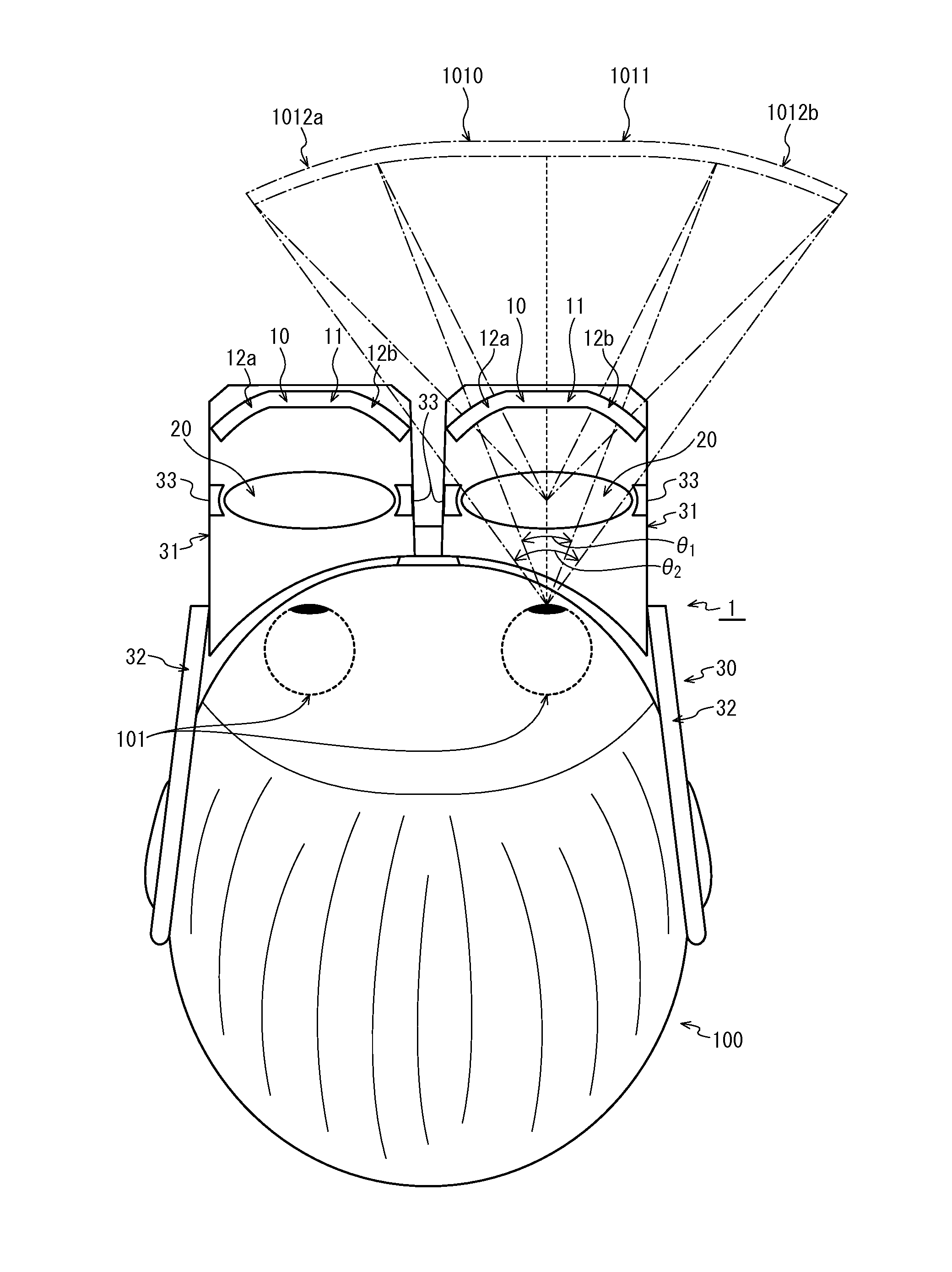
[0081]FIG. 1 shows the structure of a head-mounted display device 1 (hereinafter simply referred to as “display device 1”) pertaining to Embodiment 1. In particular, the optical system of the device is shown in this drawing.

[0082]The display device 1 includes an optical system including: an image display element 10 for displaying a two-dimensional image; and an eyepiece 20 located in front of the screen of the image display element 10, and magnifies an image displayed by the image display element 10 and projects a virtual image of the image into the air. The display device 1 also includes a holder 30 for holding the optical system and so on in front of the head 100 of the viewer. An eyeball 101 of the viewer sees, through the eyepiece 20, a magnified virtual image 1010 of the image displayed by the image display element 10. In the drawing, the magnified virtual image 1010 is projected to the location near the image display element 10 in order to simplify the drawing. In reality, how...

embodiment 2

[0153]FIG. 6 shows the structure of a head-mounted display device 2 pertaining to Embodiment 2.

[0154]The display device 2 has a similar structure to the display device as described above except that the eyepieces are not single lenses, and each eyepiece is composed of two lenses, namely a lens 20a for magnify and projecting an image displayed on the image display element 10 and a lens 20b for correction.

[0155]The lens 20b is not only used for correction of various kinds of aberration, but may also be used for correction of the visual acuity of each individual viewer. Therefore, the frame 33a supporting the lens 20b for correction is detachable. For example, the frame 33a is configured such that the lens 20b can be removed from the frame 33a by moving a frame support bar.

[0156]For example, the display device 1 pertaining to Embodiment 1 can correct myopia and hyperopia to a some extent by changing the positional relationship between the image display element 10 and the eyepieces 20. ...

embodiment 3

[0159]FIG. 7 shows the structure of a head-mounted display device 3 pertaining to Embodiment 3.

[0160]The display device 3 has a similar structure to the display device 1 except that the axis C of the optical system of the display device 3 is slanted downward with respect to the horizontal visual line H.

[0161]The horizontal visual line H represents a line that the viewer who is standing feels as being horizontal.

[0162]The following explains the effect obtained by slanting the optical system of the display device 3 downward.

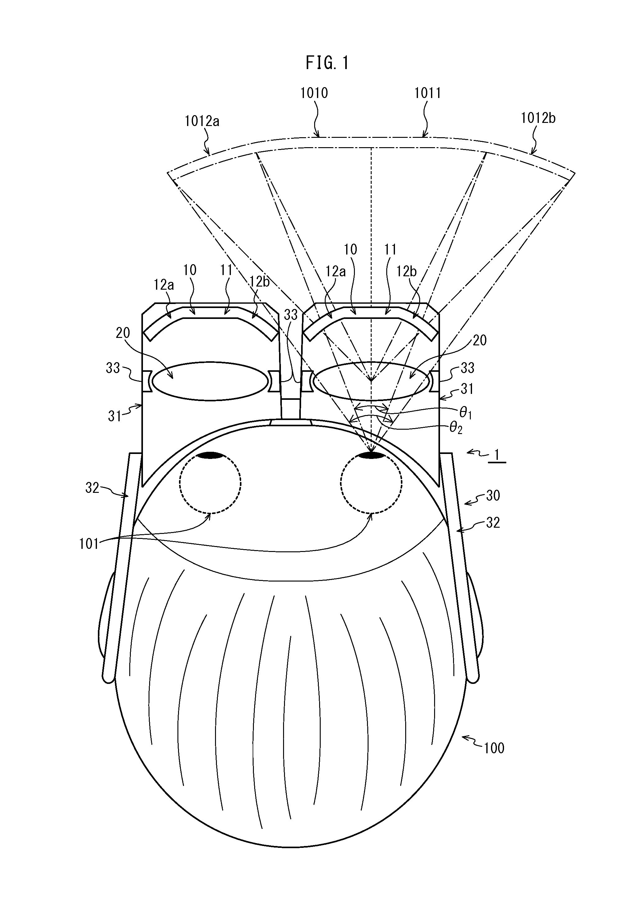
[0163]In the human characteristics with respect to perception of information within the field of view shown in FIG. 2, the left range and the right range of the field of view of a human in the horizontal direction are equal, but the upper range and the lower range in the vertical direction are not equal. Specifically, within the useful visual field (i.e. the field covered by eye movement), the upper range is 8° and the lower range is 12°. Within the induced visual ...


PUM


Abstract

A head-mounted display device having: an image display element displaying a two-dimensional image; an eyepiece magnifying and projecting the image displayed by the image display element; and a holder holding the image display element and the eyepiece, so that the viewer's eyeball sees, through the eyepiece, a magnified virtual image of the image displayed by the image display element. The image display element is a two-dimensional display device having the shape of a matrix, composed of a central portion which is flat, and a left side portion and a right side portion each of which has a sheet-like shape whose cross-section along a horizontal plane is curved toward the eyepiece away from the extension line of the central portion. In the image display element, pixels in the left and right side portions and are greater in size than pixels in the central portion.

Description

TECHNICAL FIELD[0001]The present invention relates to a head-mounted display device, and particularly to a head-mounted display device that holds a two-dimensional image display element and an eyepiece to the viewer's head and allows the viewer to see a magnified virtual image of an image displayed by the two-dimensional image display element.BACKGROUND ART[0002]In recent years, visual display devices equipped with a high-definition large screen are demanded as displays for televisions and computers. Consequently, display devices such as liquid crystal panels and plasma display panels are remarkably increasing in size.[0003]The reason for this is, for example, a display needs to have a wider angle of view in order to present a more realistic image to the viewer. In quantitative terms, it is known that in order to create a realistic effect such as a stereoscopic effect, visual impact and so on, a display needs to have a horizontal view angle of at least 30° (i.e. ±15°, which denotes ...

Claims


Application Information

Patent Timeline
Patent Type & Authority Applications(United States)
IPC IPC(8): G02B27/01
CPCG02B27/0172G02B2027/0123G02B2027/0178G02B27/017G02B2027/0156G02B2027/0161G02B27/0176
Inventor MAKINO, HIROYASUTAKATA, YUSUKE
Owner PANASONIC INTELLECTUAL PROPERTY MANAGEMENT CO LTD
Why Eureka
Try Eureka