Compact row closer and row cleaner assemblies

a technology of row cleaners and assemblies, applied in the field of agricultural equipment, can solve the problems of affecting the cleaning effect of the row cleaner, the geometry of the adjustable and floating row cleaner, and the drawbacks of the existing row cleaner, so as to achieve the effect of improving the cleaning effect of the row and the cleaning operation, and achieving the effect of improving the cleaning

Active Publication Date: 2022-02-15
MARTIN RONALD STEVE
View PDF11 Cites 1 Cited by
  • Summary
  • Abstract
  • Description
  • Claims
  • Application Information

AI Technical Summary

Benefits of technology

[0012]The present invention provides a compact parallel arm configuration that may be used in both floating row closer systems and in row cleaner systems and provides an effective and efficient solution that improves both row cleaning and row closing operations over prior art row closer / cleaning systems. Although discussed largely in the context of row closing operation in this specification, the invention is expressly stated herein as applying also to row cleaning operation and persons possessing ordinary skill in the art would appreciate and understand the use and benefits of the invention in connection with row cleaning operation.
[0013]Critically, the parallel-linkage configuration of the present invention provides a frame for supporting spading closing wheels or alternatively row clearing wheels. The parallel-linkage frame allows the row closer / cleaner to move vertically up / down relative to the ground without altering the angle of approach of the interlinked spading closing / cleaning wheels when encountering changing ground / terrain elevation. Closing / cleaning wheels have teeth configured to interlink or mesh effectively in a rotating operation to engage the ground and / or debris.

Problems solved by technology

However, there are downsides to tillage that are driving modern farmers towards “low-till” or “no-till” farming systems.
However, these existing row cleaner systems have drawbacks.
Adjustable and floating row cleaners may not possess the ideal geometry with respect to a planter to provide for optimal row cleaning action by the cleaner wheel assemblies.
Existing row closing assemblies comprise similar drawbacks and limitations to those of existing row cleaners.
Namely, existing row closing assemblies do not maintain an ideal desired geometry for closing wheels as the closing wheels and row closing assembly travel over terrain.
However, these changes in elevation cause a change in the geometry, or orientation, of the row closing wheels relative to the row being closed.
However, most cannot be adjusted at all, or if they can be adjusted they cannot be adjusted to compensate for changes in elevation over a row or seed slot.
Another problem with existing row closer wheel designs is that the relative angle of the wheels with respect to the frame can be difficult to change for any given set of closer wheels.

Method used


Image

  • Compact row closer and row cleaner assemblies
  • Compact row closer and row cleaner assemblies
  • Compact row closer and row cleaner assemblies

Examples


second embodiment

[0061]The following discussion provides example embodiments of the inventive subject matter. Although each embodiment represents a single combination of inventive elements, the inventive subject matter is considered to include all possible combinations of the disclosed elements. Thus, if one embodiment comprises elements A, B, and C, and a second embodiment comprises elements B and D, then the inventive subject matter is also considered to include other remaining combinations of A, B, C, or D, even if not explicitly disclosed.

[0062]In some embodiments, the numbers expressing quantities used to describe and claim certain embodiments of the invention are to be understood as being modified in some instances by the term “about.” Accordingly, in some embodiments, the numerical parameters set forth in the written description and attached claims are approximations that can vary depending upon the desired properties sought to be obtained by a particular embodiment. In some embodiments, the ...

first embodiment

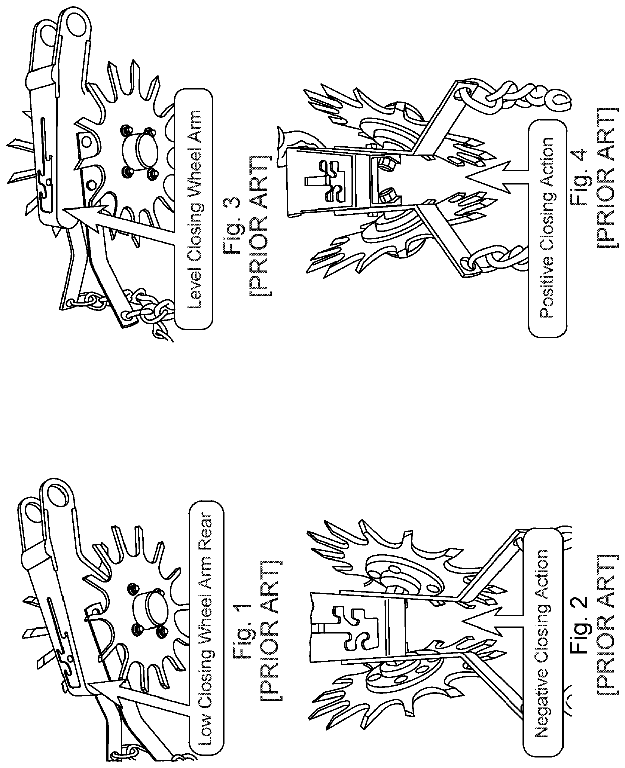
[0085]The closing wheels 50 may be angled with respect to the horizontal and / or vertical planes. The ideal orientation of the closing wheels 50 will depend on the type of planter, the type of planter row unit 20, the type of closing wheels 50, the soil conditions, the type of seed planted, and operator preferences. In the prior art closing wheel assembly shown in FIGS. 19-21, the closing wheels 50 are angled with respect to the vertical plane only, which is typical for a spiked closing wheel 50, such as that shown, in certain applications. The embodiment of the closing wheels 50 shown in FIGS. 19-21 works well in many conditions when each closing wheel 50 is angled twenty three degrees from the vertical. The angle at which the closing wheels 50 engage the ground surface when oriented as shown in FIG. 19 is substantially parallel to the furrow, but it may be orientated as depicted in FIGS. 32B and 32C, and the optimal orientation of the closing wheels 50 depend on many factors as ind...


PUM


Abstract

An apparatus and system for adjustably controlling the position and depth of row closer wheels in no-till planting applications, the apparatus comprising a frame, a piston movably secured at the top to the frame, upper and lower parallel arms disposed about the piston and movably secured at one end to the frame and at the other end to a hub stem, and a set of piston arms each movably secured at the top to one of the upper or lower parallel arms and at the other end to the bottom of the piston. A closing wheel assembly having a closing wheel frame and a set of closing wheels pivotally mounted to a lever on a single axle assembly allows the operator to change the angle at which the closing wheels intersect the ground surface during use. Accordingly, as the angle of the lever is manipulated, the angle of the closing wheel pivotally mounted to that lever changes in the vertical and / or horizontal dimensions.

Description

CROSS-REFERENCE AND CLAIM OF PRIORITY[0001]The present application claims benefit of priority to provisional applications U.S. Prov. Pat. App. No. 62 / 741,438, entitled COMPACT PARALLEL ARM ROW CLOSER AND ROW CLEANER, filed 4 Oct. 2018, Martin et al.; to U.S. Prov. Pat. App. 62 / 803,420, entitled IMPROVED ROW CLEANER / CLOSING WHEEL, filed 8 Feb. 2019, Martin et al.; and to U.S. Prov. Pat. App. No. 62 / 804,208, entitled IMPROVED ROW CLOSING WHEEL ASSEMBLY, filed 11 Feb. 2019, Martin et al., both of which are incorporated by reference herein in their entirety.FIELD OF THE INVENTION[0002]The present disclosure is generally applicable to the field of agricultural equipment, and more particularly for improved row closing and row cleaning in no-till farming applications and for improved row cleaning and for the closing of seed troughs.AUTHORIZATION PURSUANT TO 37 C.F.R. § 1.171 (d)(c)[0003]A portion of the disclosure of this patent document contains material which is subject to copyright and ...

Claims


Application Information

Patent Timeline
Patent Type & Authority Patents(United States)
IPC IPC(8): A01B63/10A01B63/00A01C5/06
CPCA01B63/004A01B63/008A01B63/10A01C5/068A01C5/066A01C7/201Y02A40/22
Inventor MARTIN, RONALD STEVEREZASOLTANI, ASGHAR
Owner MARTIN RONALD STEVE
Why Eureka
Try Eureka