Bar code scanning system with wireless communication links

Inactive Publication Date: 2002-02-28
METROLOGIC INSTR
View PDF0 Cites 28 Cited by
  • Summary
  • Abstract
  • Description
  • Claims
  • Application Information

AI Technical Summary

Benefits of technology

0036] A further object of the present invention is to provide a wireless automatic bar code symbol reading device having a housing that can be comfortably mou

Problems solved by technology

A major drawback with bar code symbol reading systems using the physical-wiring method of interconnection is that the movement of the portable hand-held laser scanning device is restricted by the overall (extended) length of the flexible cord.
In many applications, such as product inventory, the use of such bar code symbol reading systems is simply unacceptable.
While prior art bar code symbol reading systems

Method used


Image

  • Bar code scanning system with wireless communication links
  • Bar code scanning system with wireless communication links
  • Bar code scanning system with wireless communication links

Examples


Embodiment Construction

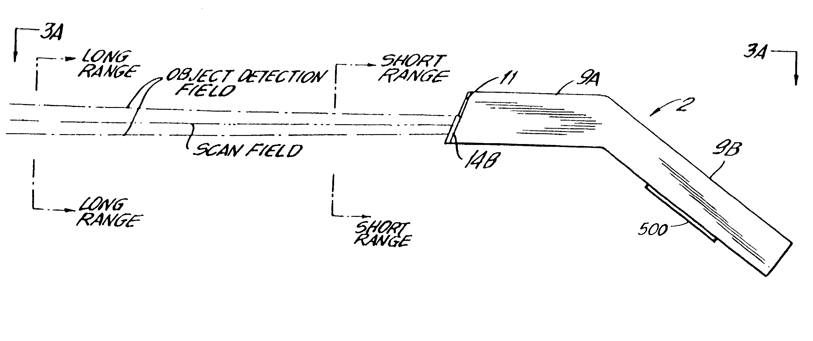
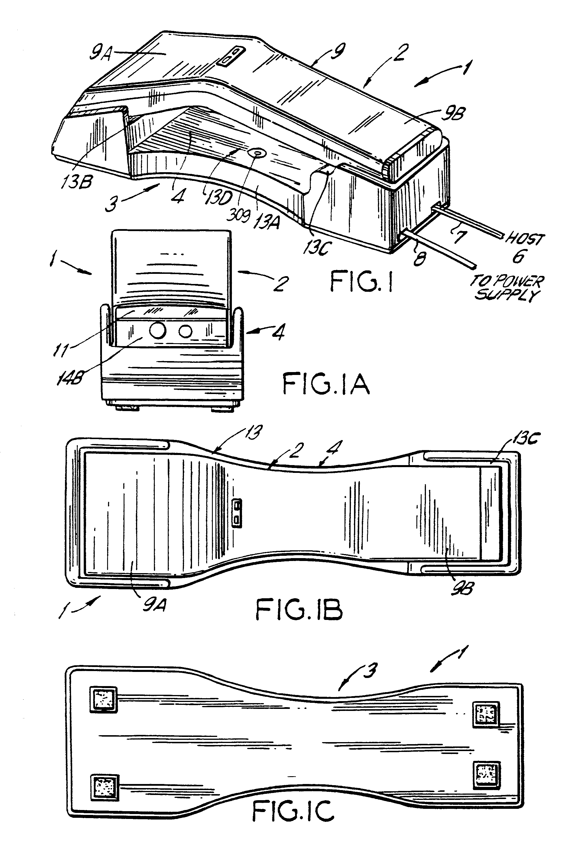
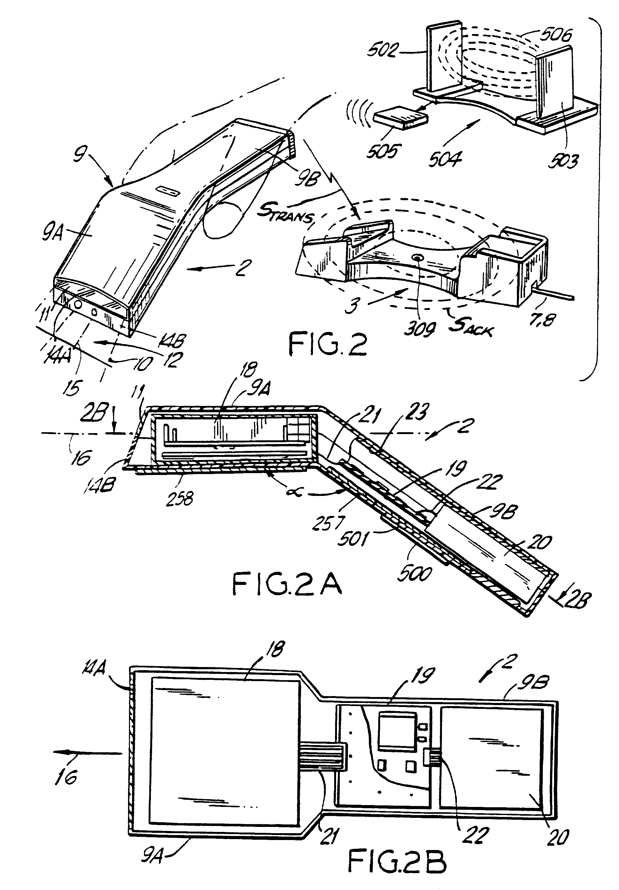
[0121] In FIGS. 1 to 6D, four different embodiments of the automatic hand-supportable bar code symbol reading system of the present invention are shown. FIGS. 1 to 3A illustrate a first embodiment of the automatic bar code symbol reading system. In FIGS. 4 to 4B, a second embodiment of the automatic bar code symbol reading system is shown. FIGS. 5 to 5C illustrate a third embodiment of the automatic bar code symbol reading system. In FIGS. 6A to 6D, a fourth embodiment of the automatic bar code symbol reading system is shown. For each of these systems, the hand-supportable bar code symbol reading device includes the automatic bar code symbol reading engine of the present invention as shown in FIGS. 7A to 7F and schematically illustrated in FIGS. 8 to 9. The operation of these embodiments of the automatic bar code symbol reading device of the present invention will now be described with reference to FIGS. 10 to 14.

[0122] As there are numerous possible embodiments of the automatic bar...


PUM


Abstract

A code symbol reading device includes a portable housing that contains a source of optical energy. This optical energy is projected into a scan field external to the housing and is incident upon a code symbol situated on an object located within the scan field. Optical energy reflected off the code symbol is detected within the housing to produce scan data that is indicative of the detected optical energy. The scan data is processed to detect and decode the code symbol and to produce symbol character data that are representative of the decoded code symbol. A data packet utilizing the symbol character data is constructed and then used to modulate an electromagnetic carrier signal that is transmitted to a base unit. At the base unit, the carrier signal is demodulated and the data packet is recovered. The received data packet is processed to recover the symbol character data, and an acknowledgment signal is generated to acknowledge the receipt of the symbol character data at the base unit.

Description

[0001] This is a Continuation of patent application Ser. No. 09 / 346,859, filed on Jul. 2, 1999, which is a Continuation of patent application Ser. No. 08 / 890,576 filed on Jul. 7, 1997, now issued as U.S. Pat. No. 6,015,091 on Jan. 18, 2000, which is a Continuation-In-Part of patent application Ser. No. 07 / 898,919, filed Jun. 12, 1992, now issued as U.S. Pat. No. 5,340,973, patent application Ser. No. 07 / 761,123, filed Sep. 17, 1991, now issued as U.S. Pat. No. 5,340,971, and patent application Ser. No. 07 / 821,917, filed on Jan. 16, 1992, now abandoned, and a Continuation of patent application Ser. No. 08 / 292,237 filed on Aug. 17, 1994, now issued as U.S. Pat. No. 5,808,284; said patent application Ser. No. 07 / 761,123 being a Continuation-In-Part of patent application Ser. No. 07 / 583,421, filed on Sep. 17, 1990, and now issued as U.S. Pat. No. 5,260,553.[0002] 1. Field of the Invention[0003] The present invention relates generally to bar code symbol reading systems and, more specific...

Claims


Application Information

Patent Timeline
IPC IPC(8): G02B26/10G06K7/10G06K7/14G06K17/00
CPCG02B26/106G06K7/10G06K7/10564G06K7/10584G06K7/10594G06K7/10603G06K7/10663G06K7/10673G06K7/10693G06K7/10702G06K7/10792G06K7/10801G06K7/10811G06K7/10851G06K7/10861G06K7/10871G06K7/10881G06K7/10891G06K7/109G06K7/14G06K7/1443G06K17/0022G06K2007/10534G06K2207/1012G06K2207/1016G06K2207/1017G06K2207/1018
Inventor KNOWLES, CARL H.ROCKSTEIN, GEORGE B.WILZ, DAVID M. SR.COLAVITO, STEPHEN J.GERMAINE, GENNADY
Owner METROLOGIC INSTR
Why Eureka
Try Eureka