System for reading bar code symbols using portable bar code symbol readers having one-way RF signal transmission links with base stations

a bar code symbol and portable technology, applied in the field of can solve the problems of inability to use such bar code symbol reading systems, limited hand-held laser scanning devices, and inability to move, etc., and achieve the effect of greater hand mobility

Inactive Publication Date: 2002-03-21
METROLOGIC INSTR
View PDF0 Cites 31 Cited by
  • Summary
  • Abstract
  • Description
  • Claims
  • Application Information

AI Technical Summary

Benefits of technology

0034] A further object of the present invention is to provide a wireless automatic bar code symbol reading device having a housing that can be comfortably mounted to the wrist of its user, similar to a wrist bracelet or a watch, and which can be reconfigured when not in use to provide its user greater hand mobility.

Problems solved by technology

A major drawback with bar code symbol reading systems using the physical-wiring method of interconnection is that the movement of the portable hand-held laser scanning device is restricted by the overall (extended) length of the flexible cord used.
In many applications, such as product inventory, the use of such bar code symbol reading systems is simply unacceptable.
While prior art bar code symbol reading systems employing the wireless method of interconnection offer a marked degree of flexibility over systems utilizing the physical wiring method of interconnection, such prior art systems nevertheless suffer from a number of shortcomings and drawbacks.
In particular, these prior art systems require two-way packet communications which involves the use of complex data communications protocols and a separate transmitter and a receiver (i.e., transceiver) at each hand-held bar code symbol reader and base unit in the system.
Typically, these data communications requirements increase the cost of manufacture of such systems, and substantially increase the electrical power consumption at each hand-held bar code symbol reader.

Method used


Image

  • System for reading bar code symbols using portable bar code symbol readers having one-way RF signal transmission links with base stations
  • System for reading bar code symbols using portable bar code symbol readers having one-way RF signal transmission links with base stations
  • System for reading bar code symbols using portable bar code symbol readers having one-way RF signal transmission links with base stations

Examples


Embodiment Construction

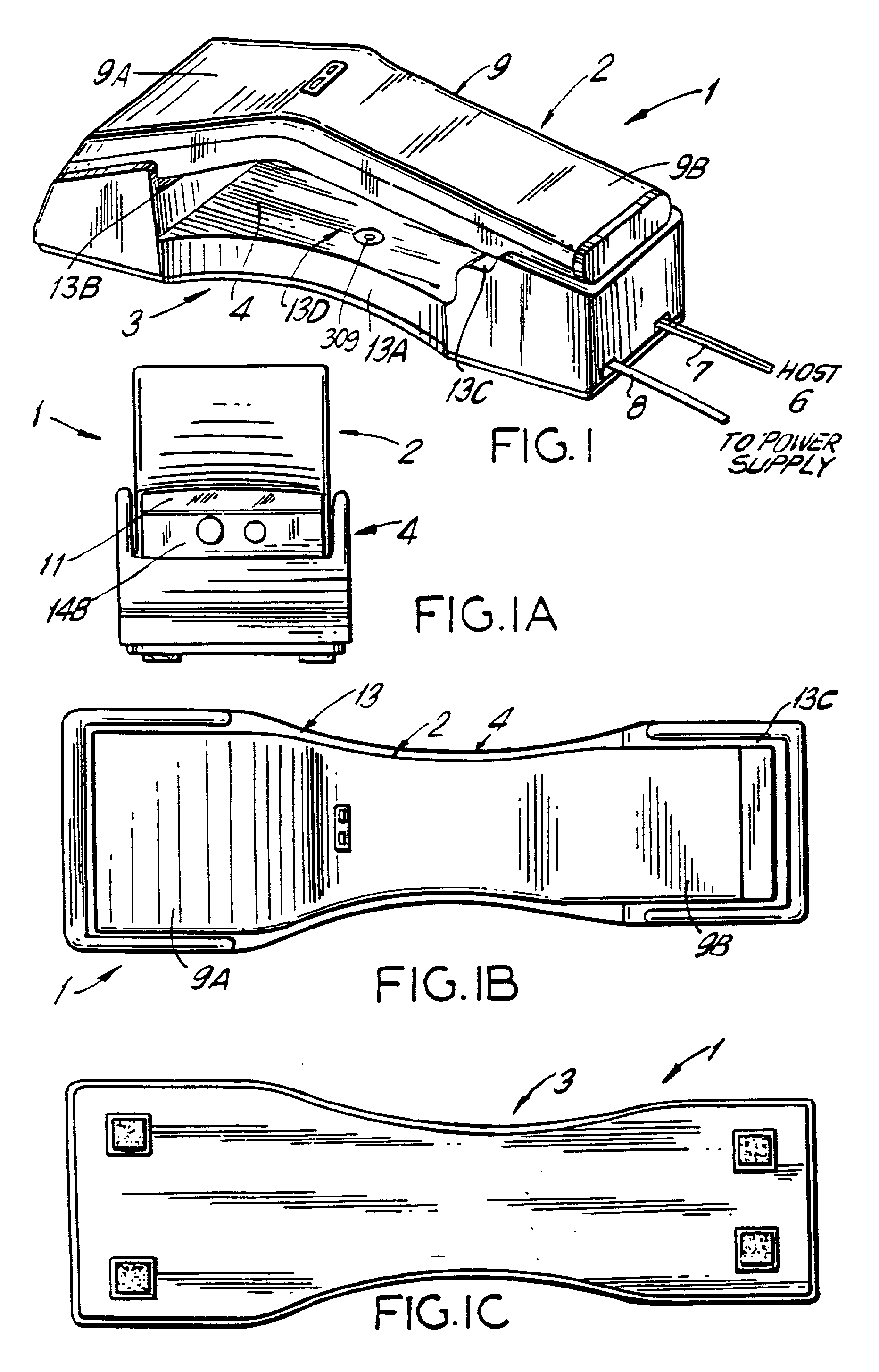
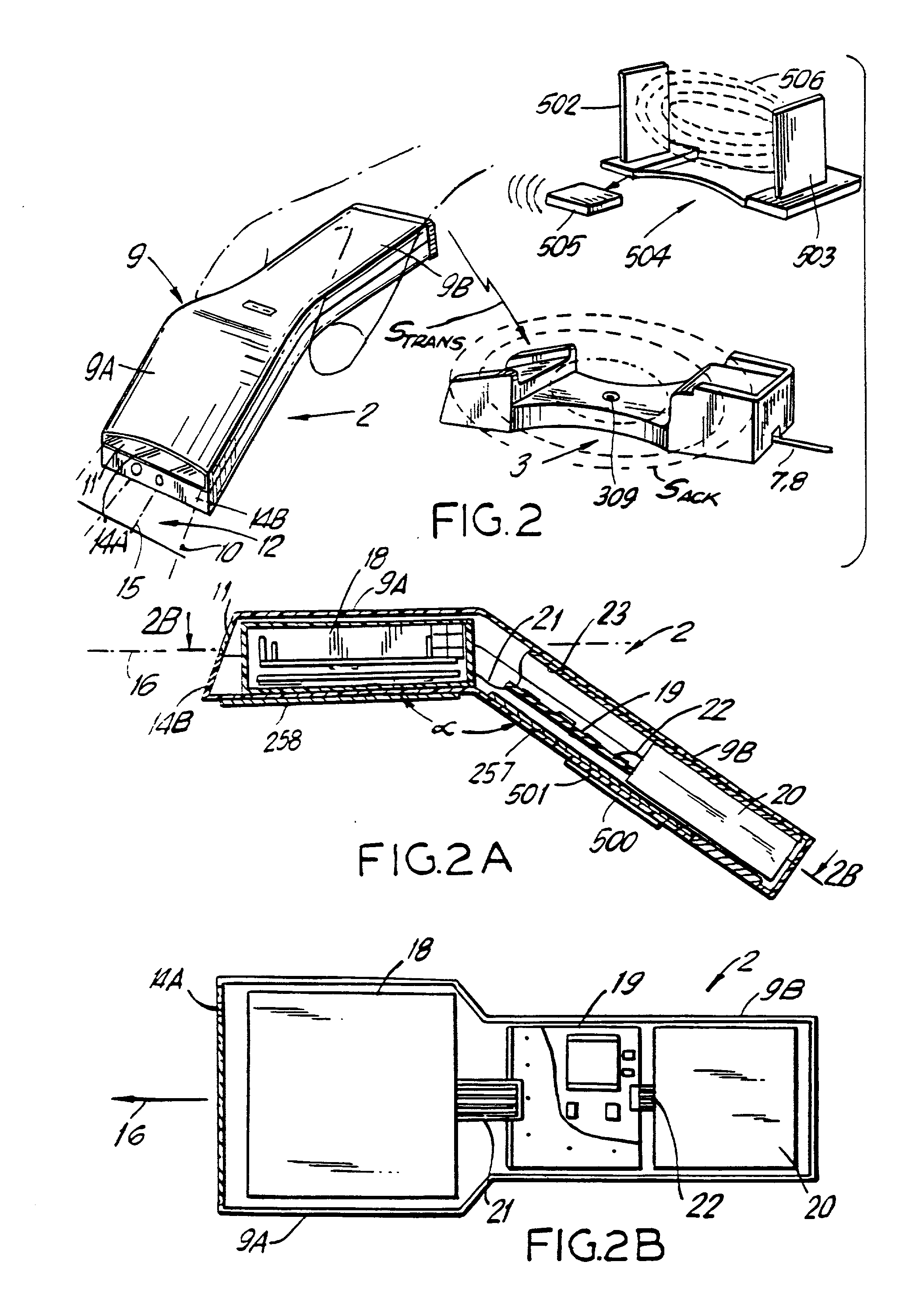
[0118] In FIGS. 1 to 6D, four different embodiments of the automatic hand-supportable bar code symbol reading system of the present invention are shown. In FIGS. 1 to 3A, the first embodiment of the automatic bar code symbol reading system is illustrated. In FIGS. 4 to 4B, the second embodiment of the automatic bar code symbol reading system is illustrated. In FIGS. 5 to 5C, the third embodiment of the automatic bar code symbol reading system is illustrated. In FIGS. 6A to 6D, the fourth embodiment of the automatic bar code symbol reading system is illustrated. In each of these systems, the hand-supportable bar code symbol reading device includes the automatic bar code symbol reading engine of the present invention shown in FIGS. 7A to 7F and schematically illustrated in FIGS. 8 to 9, in particular. The operation of these embodiments of the automatic bar code symbol reading device of the present invention will be described with reference to FIGS. 10 to 14.

[0119] As there are numerou...


PUM


Abstract

A code symbol reading device includes a portable housing that contains a light source. Light from the light source is projected into a scan field external to the housing and onto a code symbol on an object located within the scan field. The light reflected off the code symbol is detected within the housing to produce scan data that is indicative of the detected light intensity. The scan data is processed to detect and decode the code symbol and to produce symbol character data that are representative of the decoded code symbol. A data packet utilizing the symbol character data is synthesized and modulated onto a carrier signal that is transmitted to a base unit where the carrier signal is demodulated and the data packet recovered. The received data packet is analyzed to recover the symbol character data, and an acknowledgment signal is produced to acknowledge the receipt of the symbol character data at the base unit.

Description

[0001] This is a Continuation of patent application Ser. No. 09 / 346,859, filed on Jul. 2, 1999, which is a Continuation-In-Part of patent application Ser. No. 07 / 761,123 filed on Sep. 17, 1991, and now issued as U.S. Pat. No. 5,340,971.[0002] 1. Field of the Invention[0003] The present invention relates to bar code symbol reading systems having one or more base stations or units, and one or more hand-held bar code symbol reading devices each remotely suitable from the base station(s) and capable of sending symbol character data over distance(s) thereto.[0004] 2. Brief Description of the Prior Art[0005] Bar code symbols have become widely used in many commercial environments such as, for example, point-of-sale (POS) stations in retail stores and supermarkets, inventory and document tracking, and diverse data control applications. To meet the growing demands of this recent technological innovation, bar code symbol readers of various types have been developed for scanning and decoding ...

Claims


Application Information

Patent Timeline
Patent Type & Authority Applications(United States)
IPC IPC(8): G06K7/10G06K7/14G06K17/00
CPCG06K7/10G06K7/10564G06K7/10594G06K7/10603G06K7/10693G06K7/10702G06K7/10792G06K7/10801G06K7/10851G06K7/10861G06K7/10881G06K7/10891G06K7/14G06K7/1443G06K17/0022G06K2207/1012G06K2207/1016G06K2207/1017G06K2207/1018
Inventor KNOWLES, CARL H.ROCKSTEIN, GEORGE B.WILZ, DAVID M. SR.COLAVITO, STEPHEN J.GERMAINE, GENNADY
Owner METROLOGIC INSTR
Why Eureka
Try Eureka