Flow generator with patient reminder

a technology of patient reminder and flow generator, which is applied in the direction of valve operating means/releasing devices, instruments, etc., can solve the problems of foam deformation and time-consuming, and the use of foam in the air path is difficult, and achieves the effect of simple and economical construction and convenient us

Active Publication Date: 2010-07-29
JOHN SNOW & COMPANY +1
View PDF107 Cites 66 Cited by
  • Summary
  • Abstract
  • Description
  • Claims
  • Application Information

AI Technical Summary

Benefits of technology

[0008]One of the objects of the invention is to provide a simple and compact breathable gas supply apparatus incorporating a humidifier which is simple and economic in its construction, compact, and easy to use. Other objects and advantages of the invention will be described throughout the specification.

Problems solved by technology

However, in seeking to reduce the size of the CPAP machines there has been a trade-off between reduced size on the one hand and reduced performance and / or increased noise on the other, for example Malinckrodt / Tyco / Puritan Bennett ‘Goodnight’ Series.
Another problem with some flow generators is extensive use of foam in the air path for sound absorption.
The foam can degrade with time.

Method used


Image

  • Flow generator with patient reminder
  • Flow generator with patient reminder
  • Flow generator with patient reminder

Examples


Embodiment Construction

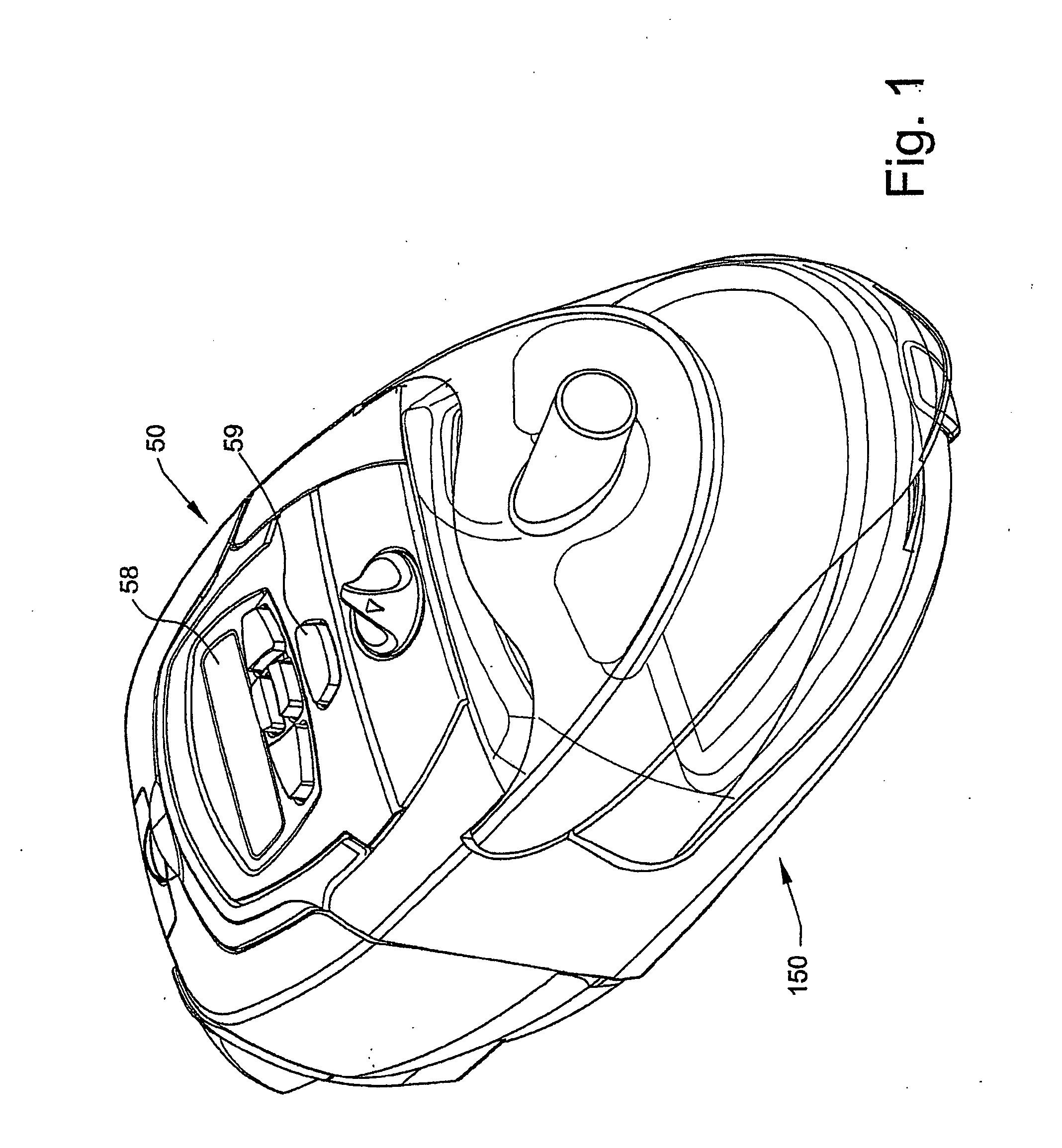
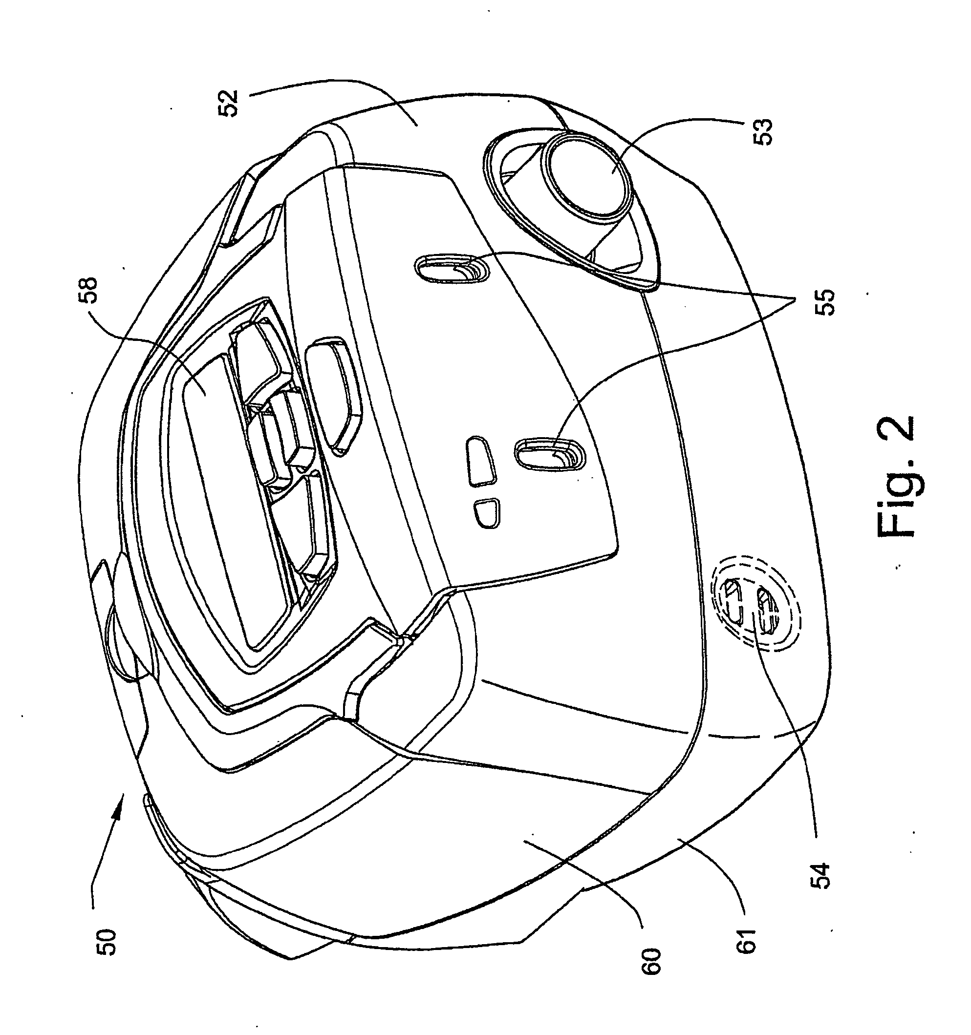
[0116]The illustrated apparatus comprises a flow generator 50 and a humidifier 150, shown in their assembled condition in FIG. 1, and separately in FIGS. 2 and 3 respectively. As shown in FIG. 2, the flow generator engages with the separable humidifier at an engagement face 52, from which protrudes an air connector 53 for the delivery of air from the fan to the humidifier container, electrical connectors 54 for the delivery of power to the humidifier heater and an optical coupling transmitter 200 and sensor 201 described further below.

[0117]The face 52 also carries a pair of slots 55 which are engaged by corresponding tongues 156 provided on the humidifier engagement face 157 (FIG. 15) by which the flow generator 50 and humidifier 150 are connected together, as will be described in more detail below.

Flow Generator

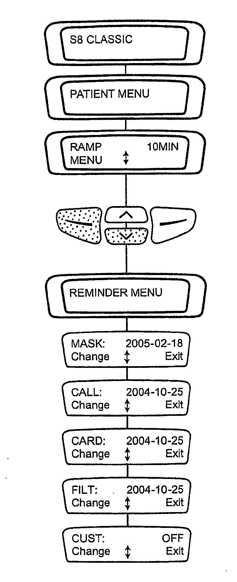
[0118]Externally, the flow generator 50 is also provided with an LCD screen 58 and associated keys 59 by which the user can set the operating parameters of the unit.

Flow Ge...


PUM


Abstract

A flow generator and humidifier construction is described, including a flow generator construction adapted to reduce noise output compared to known flow generators of comparable size. The flow generator includes a chassis forming first and second muffler volumes and a venturi-shaped connection portion, and a metal/polymer composite material blower enclosure which suppresses noise from the blower. The flow generator may be programmed to include a reminder system including a menu from which the user may request a reminder to take specific action, e.g., replace a component, call a physician, and/or enter patient data card, etc.

Description

BACKGROUND OF THE INVENTION[0001]1. Field of the Invention[0002]This invention relates to breathable gas supply apparatus, and particularly but not exclusively to such apparatus for use in Continuous Positive Airway Pressure (CPAP) treatment of conditions such as Obstructive Sleep Apnea (OSA) and other respiratory disorders and diseases such as emphysema. It will be described herein in its application to CPAP treatment apparatus, but it is to be understood that the features of the invention will have application to other fields of application, such as mechanical ventilation and assisted respiration.[0003]2. Description of Related Art[0004]CPAP treatment of OSA, a form of Noninvasive Positive Pressure Ventilation (NIPPV), involves the delivery of a pressurised breathable gas, usually air, to a patient's airways using a conduit and mask. Gas pressures employed for CPAP typically range from 4 cm H2O to 28 cm H2O, at flow rates of up to 180 L / min (measured at the mask), depending on pat...

Claims


Application Information

Patent Timeline
Patent Type & Authority Applications(United States)
IPC IPC(8): G06F3/048A61M16/00A61M16/16A62B9/00
CPCA61M16/0051A61M16/0057A61M16/0066A61M16/16A61M2205/14B29L2031/753A61M2205/50A61M2205/502A61M2205/52A62B9/003A61M2205/42A61M16/107A61M16/024
Inventor JEHA, SIMONE MARIEMURRAY, ANDREW CHARLESPAYNE, MARK JOHN
Owner JOHN SNOW & COMPANY
Why Eureka
Try Eureka