Device for mobile terminal

a mobile terminal and antenna technology, applied in the field of mobile terminals, can solve the problems of large coupling between antennas, large space requirements, and unpractical mobile terminals

Inactive Publication Date: 2002-06-06
TELEFON AB LM ERICSSON (PUBL)
View PDF5 Cites 7 Cited by
  • Summary
  • Abstract
  • Description
  • Claims
  • Application Information

AI Technical Summary

Problems solved by technology

A disadvantage with the antenna arrangement in WO97/41619 is that it requires a relatively large amount of space, and is therefore unpractical for mobile terminals, meeting size demands present today.
There is also a risk for large coupling between the antennas, when these are located in t

Method used


Image

  • Device for mobile terminal
  • Device for mobile terminal
  • Device for mobile terminal

Examples


Embodiment Construction

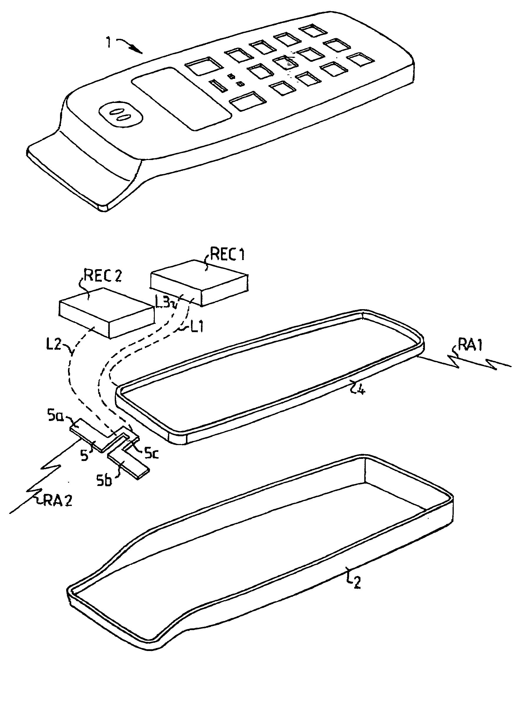
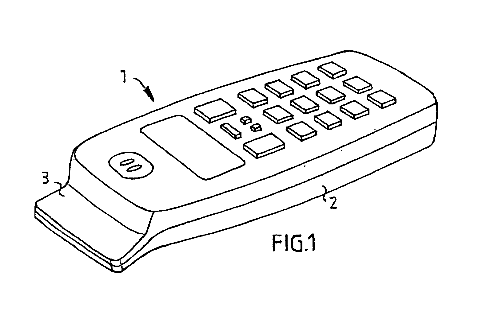
[0021] FIG. 1 shows a mobile terminal 1, equipped with an antenna arrangement according to a preferred embodiment of the present invention. The mobile terminal 1 comprises a main casing 2, having an extended shape. An antenna housing 3 is located at one end of the main casing 2. Alternatively, the mobile terminal 1 is not equipped with a separate antenna housing 3, rather all components of the antenna system are located within the main casing 2. Also, as will be described below, the casing 2 itself could form a part of the antenna system.

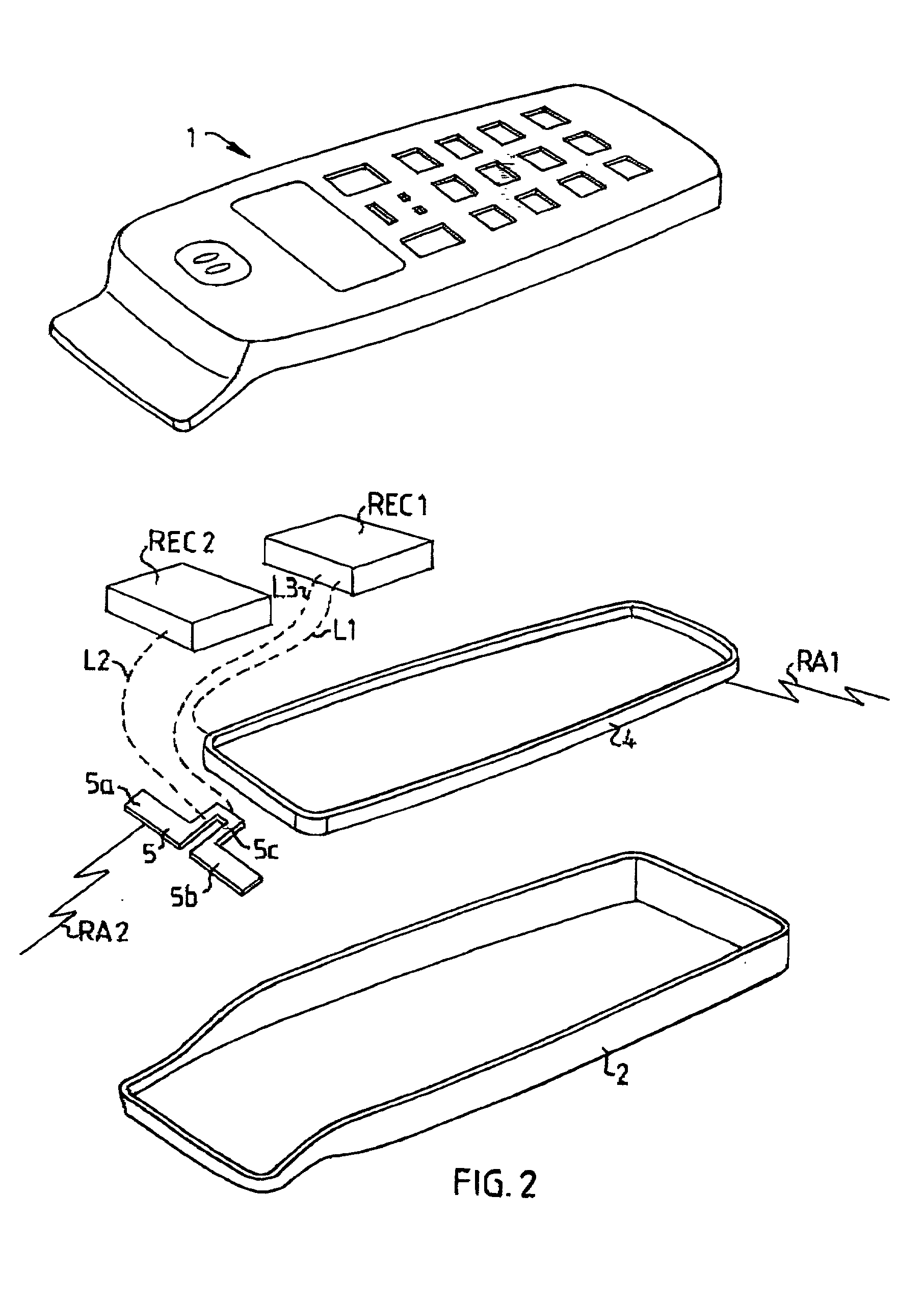
[0022] FIG. 2 shows an exploded view of the mobile teal 1 in FIG. 1. For a first radio application RA1, preferably communication between the mobile terminal 1 and a base station in a cellular telephone network, the mobile terminal 1 is provided with first radio electronic circuits REC1. The first radio electronic circuits REC1 are connected to an end-fed antenna 4, the connection being illustrated by the broken line L1. According to the preferred em...


PUM


Abstract

The invention relates to a mobile terminal antenna system for a first radio application (RA1) and a second radio application (RA2) the system comprising first radio electronic circuits (REC1) for the first radio application (RA1), and second radio electronic circuits (REC2) for the second radio application (RA2). The system also comprises an end-fed antenna (4) for the first radio application (RA1), the end-fed antenna (4) having an extended shape and being connected to the first radio electronic circuits (REC1). The system comprises a dipole antenna (5) for the second radio application (RA2), the dipole antenna (5) being located near one end of the end-fed antenna (4) and connected to the second radio electronic circuits (REC2). The first radio electronic circuits (REC1) are connected to the dipole antenna (5), whereby the end-fed antenna (4) is adapted to be fed, during transmission, against the dipole antenna (5) by the first radio electronic circuits (REC1), whereby the dipole antenna (5) is adapted to serve as a counterpoise for the end-fed antenna (4).

Description

[0001] The present invention refers to a mobile terminal antenna system according to the preamble of claim 1.DESCRIPTION OF RELATED ART[0002] In mobile terminal technology there is a requirement for the terminals to be as small as possible. Another requirement is for the antenna system to be equipped to use two or more widely separated frequency bands, whereby the effectiveness of the antenna is strongly linked to the dimensions of the latter. It is favorable to use an antenna having an electrical length in the region of a multiple of a half wavelength of the frequency to be used.[0003] In addition to these requirements, some mobile terminals are designed to include a receiver for a satellite navigation system, such as the Global Positioning System (GPS). In the known art there are different solutions regarding the antenna system for such mobile terminals.[0004] In the patent application WO97 / 41619, an antenna arrangement is disclosed, comprising one antenna for cellular communicati...

Claims


Application Information

Patent Timeline
IPC IPC(8): H01Q1/24H01Q9/16H01Q9/28H01Q9/40H01Q21/29
CPCH01Q1/242H01Q9/16H01Q21/29H01Q9/40H01Q9/285
Inventor LINDELL, BO
Owner TELEFON AB LM ERICSSON (PUBL)
Why Eureka
Try Eureka