Fill fitting for a fluid storage tank

Inactive Publication Date: 2010-11-11
MARMIT PLASTICS
View PDF12 Cites 0 Cited by
  • Summary
  • Abstract
  • Description
  • Claims
  • Application Information

AI Technical Summary

Benefits of technology

[0007]A fill fitting and filling assembly are provided for use in fluid delivery and removal from a st

Problems solved by technology

In any application, spillage of fluid and/or direct venting of gases from the tank to ambient air is generally undesirable.
Unfortunately, steel tanks are expensive to manufacture and transport, and are also susceptible to corrosion, with the potential risk of tank failure.
Further, steel tanks are typical

Method used


Image

  • Fill fitting for a fluid storage tank
  • Fill fitting for a fluid storage tank
  • Fill fitting for a fluid storage tank

Examples


Embodiment Construction

[0051]Generally, the present invention provides a fitting for attachment to a fluid storage tank. The fitting divides a single, circular tank opening into two independent fluid conduits to / from the tank. A method for filling a tank to which the fitting is attached is also described.

Overview

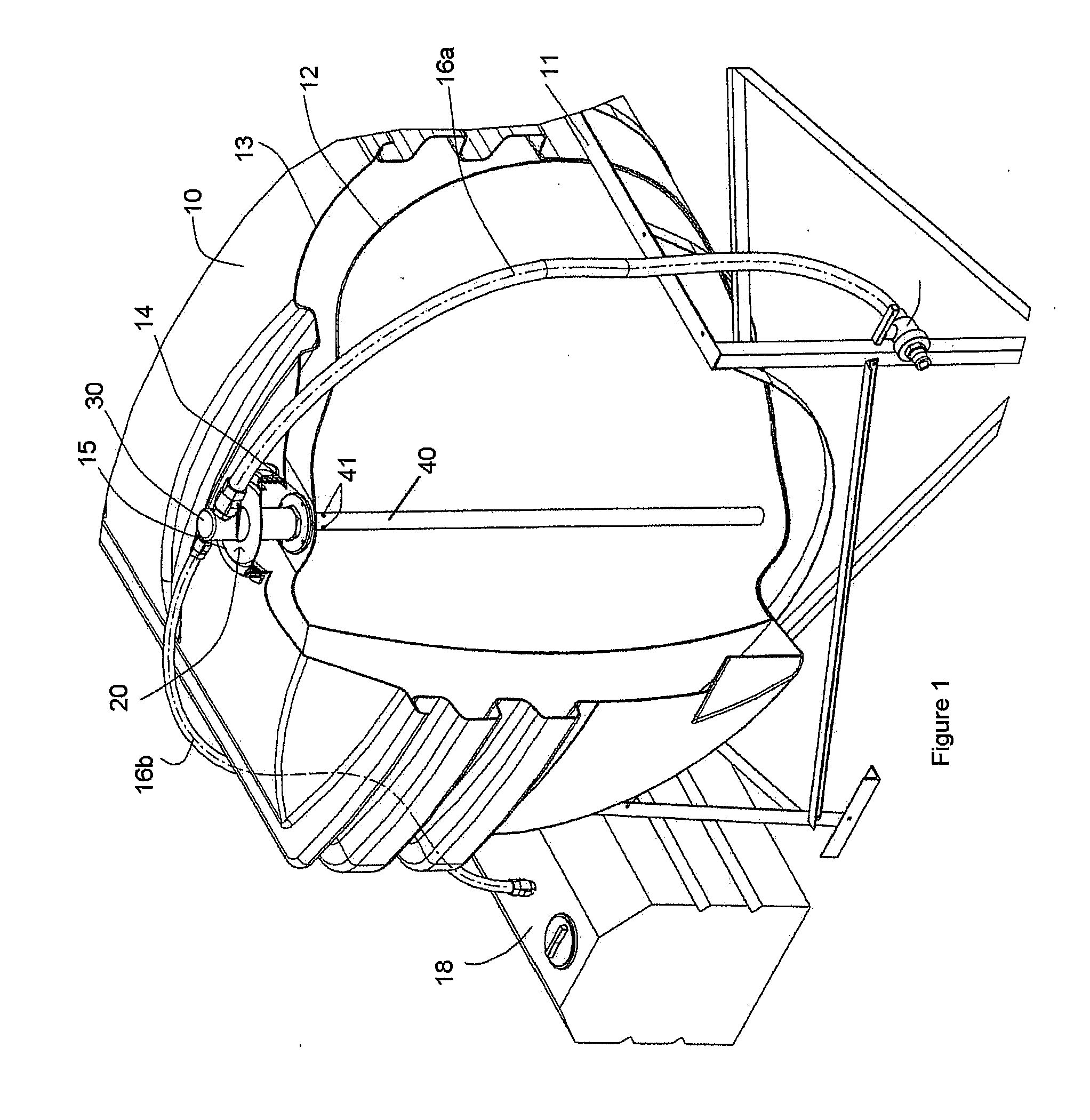
[0052]With reference to FIG. 1, a fluid storage tank 10 is shown supported on a stand 11. The tank 10 is double-walled (tank walls 12, 13), and each wall includes an opening 14, 15 to permit filling and emptying of the tank 10. A fill fitting 20 is sealably attached to the inner tank opening 14, and protrudes through the outer tank opening 15.

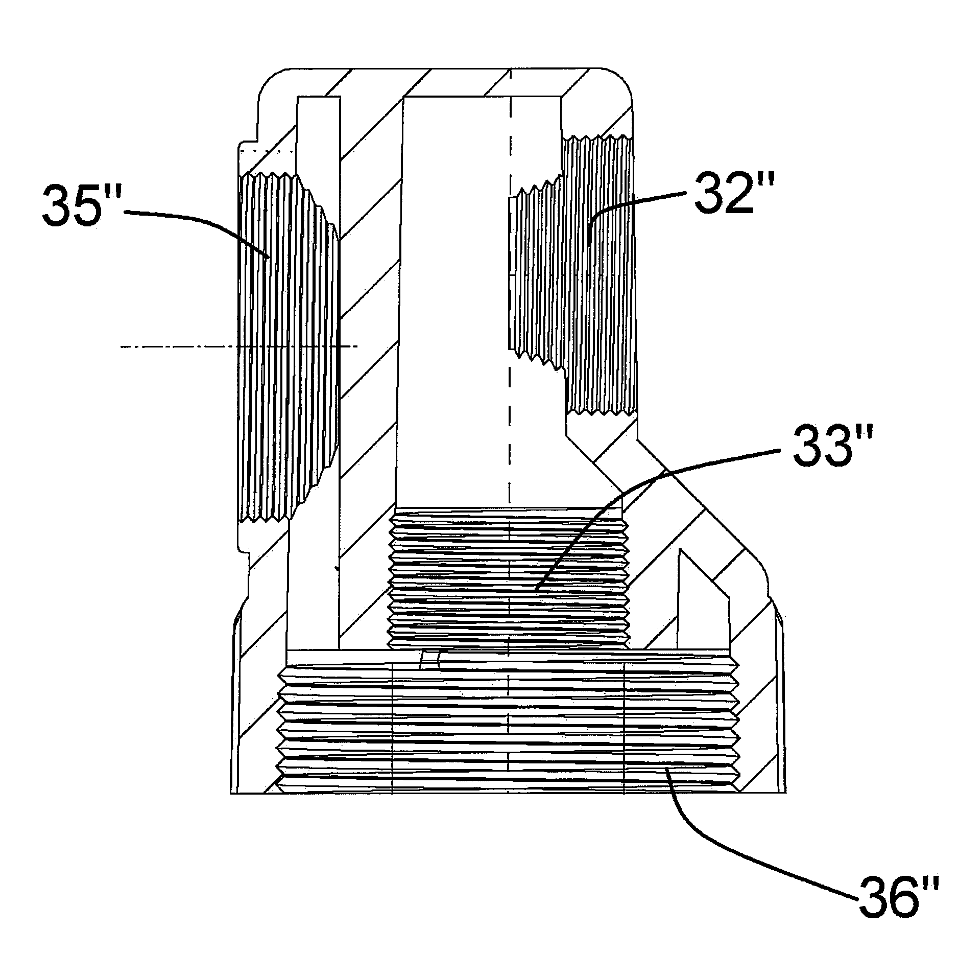
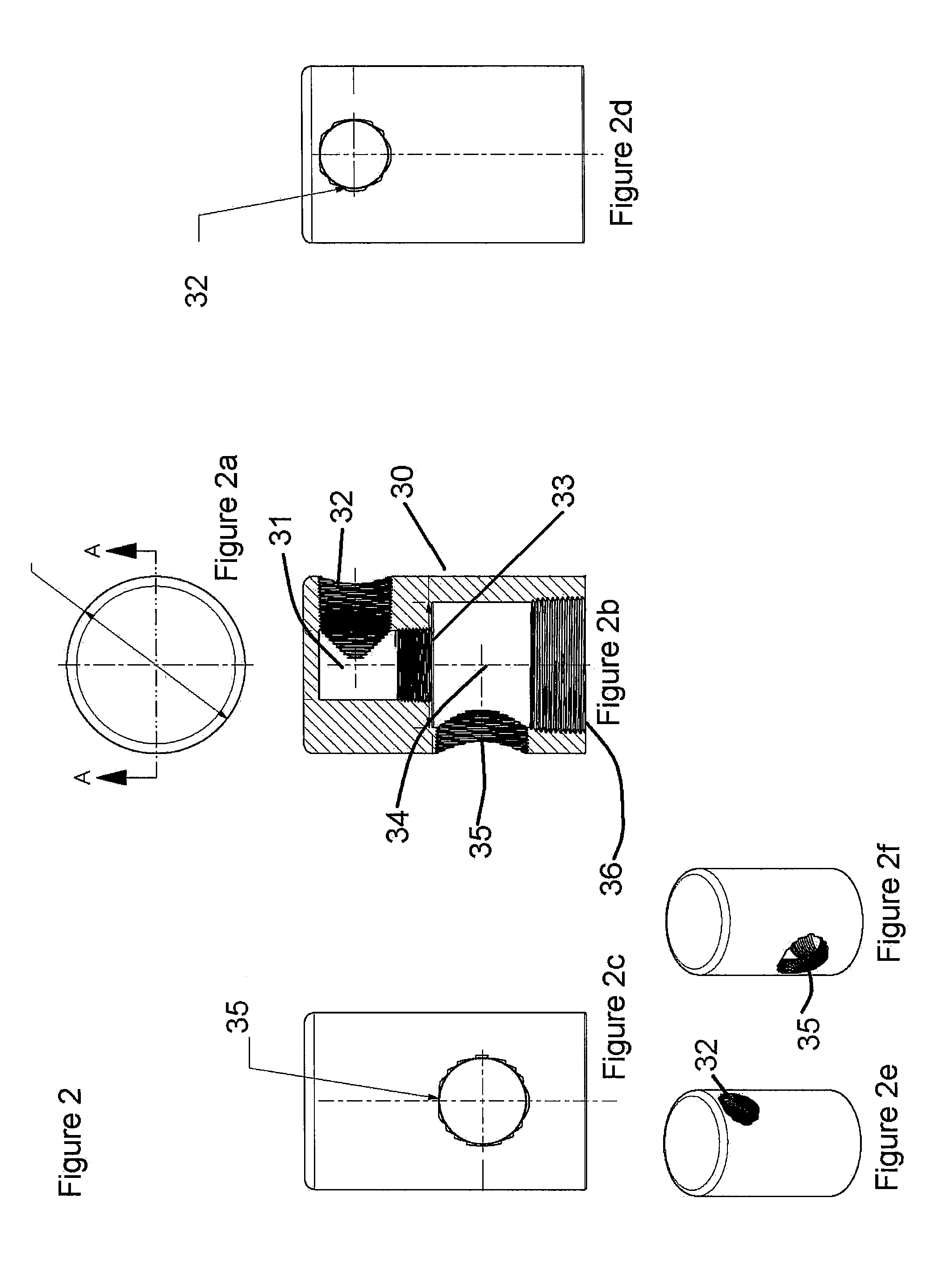
[0053]The manifold 30 of the fill fitting 20 is configured to provide two independent fluid conduits continuous with the tank interior, each extending beyond the tank outer wall 13 so as to be accessible to a user. The fluid conduits exit the manifold 30 on opposing sides at threaded manifold openings 32, 35.

[0054]External hoses 16a, 16b, are attached to mani...


PUM

PropertyMeasurementUnit
Flow rateaaaaaaaaaa
Lengthaaaaaaaaaa
Areaaaaaaaaaaa

Abstract

A fitting is provided for attachment to an outlet of a fluid storage tank. The fitting divides the opening into two fluid pathways for independent use in filling and venting of the tank. The fitting prevents spillage and improves site safety at the tank location. The fitting comprises a manifold for attachment to the tank opening, and the manifold is divided into two internal pathways from the tank opening to the exterior environment. A stinger tube is attachable to one of the pathways and extends into the tank to deliver fluid. The stinger includes a siphon break for use in standardizing tank fill levels and in emptying fluid from the manifold to avoid site spillage of tank contents.

Description

FIELD OF THE INVENTION[0001]The present invention relates generally to the filling and emptying of fluid storage tanks. More particularly, the present invention relates to a device useful in preventing tank overfilling and spillage when adding or removing fluids to / from a storage tank.BACKGROUND OF THE INVENTION[0002]Large chemical storage tanks are generally used for containment of industrial process fluids, including water, chemicals, and gases. Many industries use storage tanks only within local plants, while others may store fluids at more remote locations, which may be outdoors. In any application, spillage of fluid and / or direct venting of gases from the tank to ambient air is generally undesirable. Precautions must therefore be taken when connecting lines to the tank, and when filling or emptying the tank, to avoid leaks, spills, and other potentially hazardous site conditions.[0003]Typically, steel tanks have been used to store large volumes of fluid and volatile chemicals. ...

Claims


Application Information

Patent Timeline
IPC IPC(8): B65B3/18F16K24/04B65D85/00
CPCB65D88/54B65D90/34Y10T137/3084
Inventor POTTS, KEVIN
Owner MARMIT PLASTICS
Why Eureka
Try Eureka