Head for injecting liquid under pressure to excavate the ground

a technology of injection head and liquid under pressure, which is applied in the direction of fluid removal, cleaning apparatus, soil preservation, etc., can solve the problems of poor active radius of the jet of liquid under pressure for forming a column, a large distance from the nozzle, and a rapid loss of effectiveness of the jet in eroding soil, etc., to achieve the effect of improving the quality of the jet delivered

Inactive Publication Date: 2002-08-15
CIE DU SOL
View PDF0 Cites 10 Cited by
  • Summary
  • Abstract
  • Description
  • Claims
  • Application Information

AI Technical Summary

Benefits of technology

0008] An object of the present invention is to provide an injection head, in particular for performing jet grouting, which makes it possible to further improve the quality of the jet delivered by the nozzle(s) of the injection head mounted at the bottom end of the drill string.

Problems solved by technology

However, even with such nozzles, it is found that the jet quickly loses effectiveness in eroding the soil, such that considerable levels of kinetic energy are necessary so that when the drill string is moved in translation and optionally in rotation, the soil is eroded at a considerable distance away from the nozzle, e.g. at a distance of several decimeters (dm).
The active radius of the jet of liquid under pressure for forming a column, a sector of a column, or a plane element generally remains poor, lying in the range a few decimeters to 1 meter (m) or 2 m depending on the method implemented, on the nature of the soil, and on the energy deployed.
The solution described in the above-mentioned American patent is therefore not entirely satisfactory.

Method used


Image

  • Head for injecting liquid under pressure to excavate the ground
  • Head for injecting liquid under pressure to excavate the ground
  • Head for injecting liquid under pressure to excavate the ground

Examples


Embodiment Construction

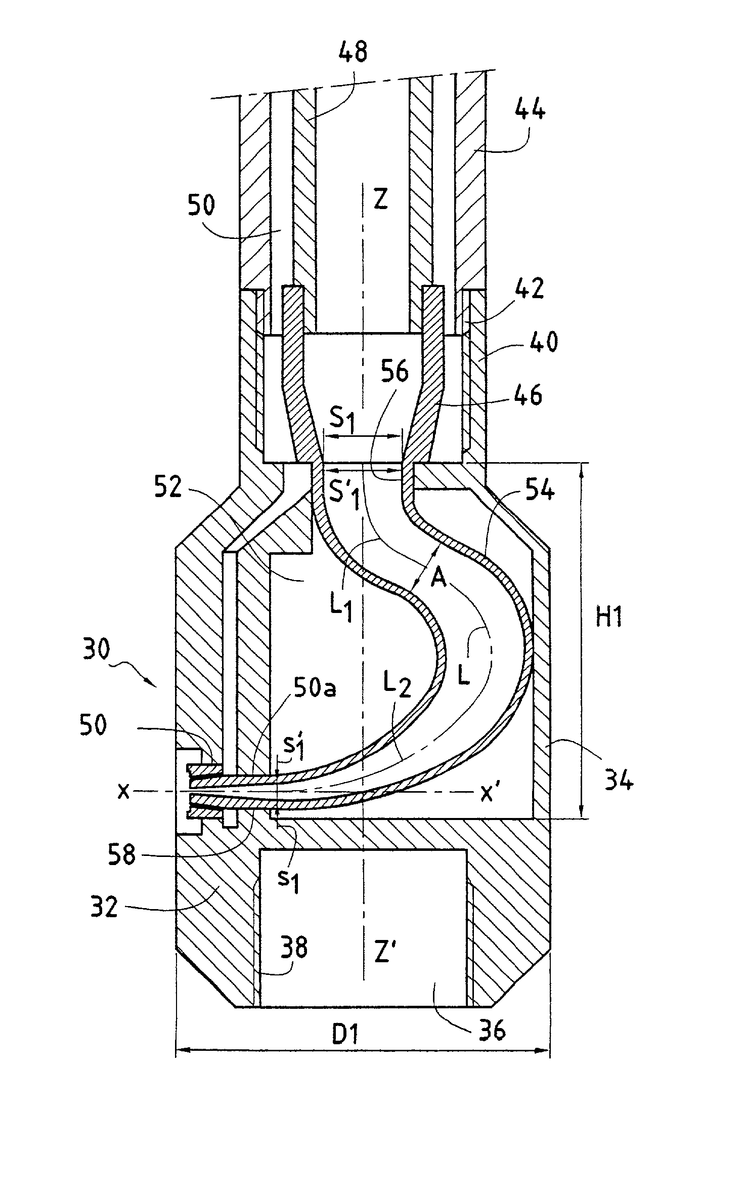
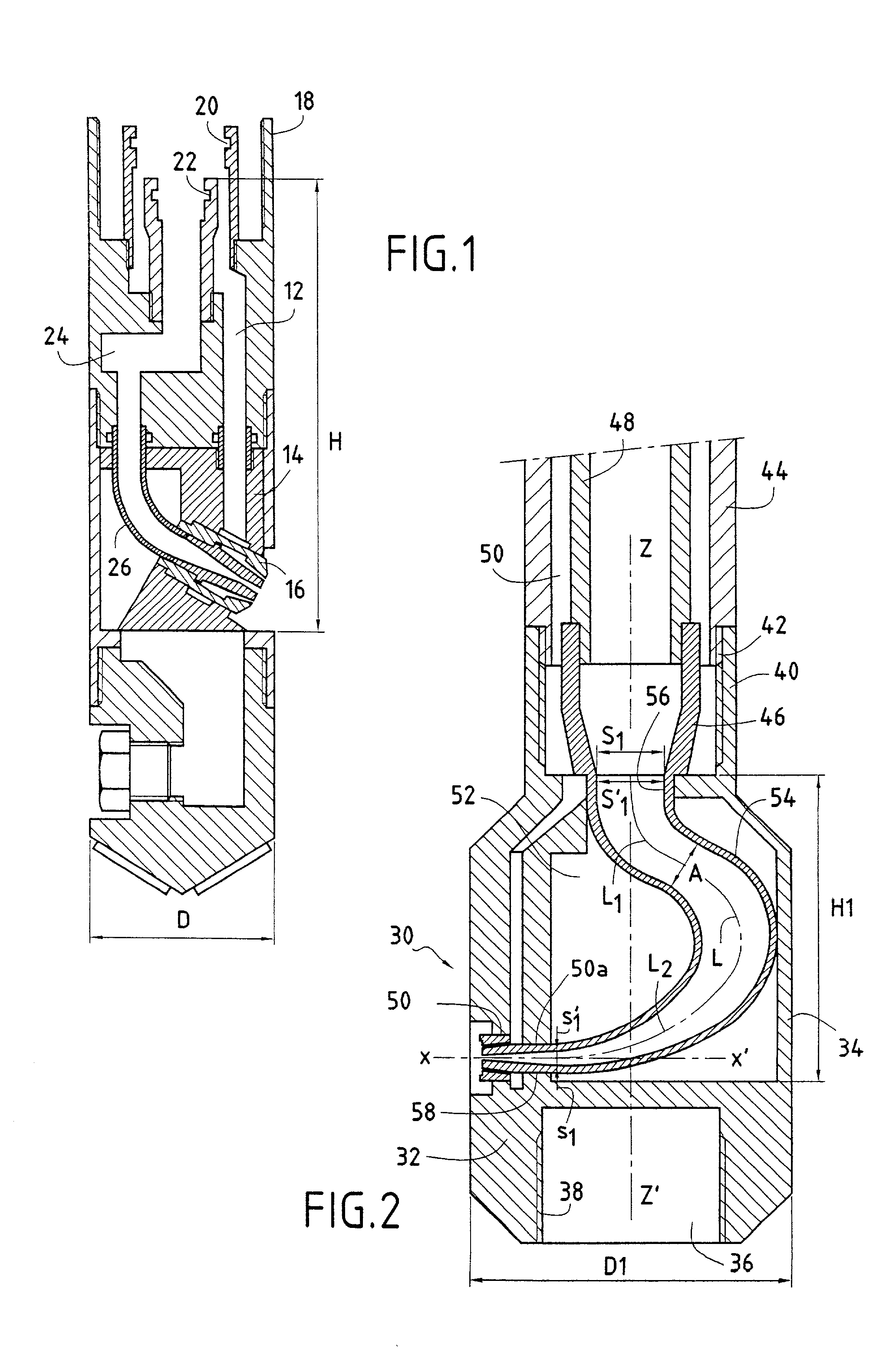
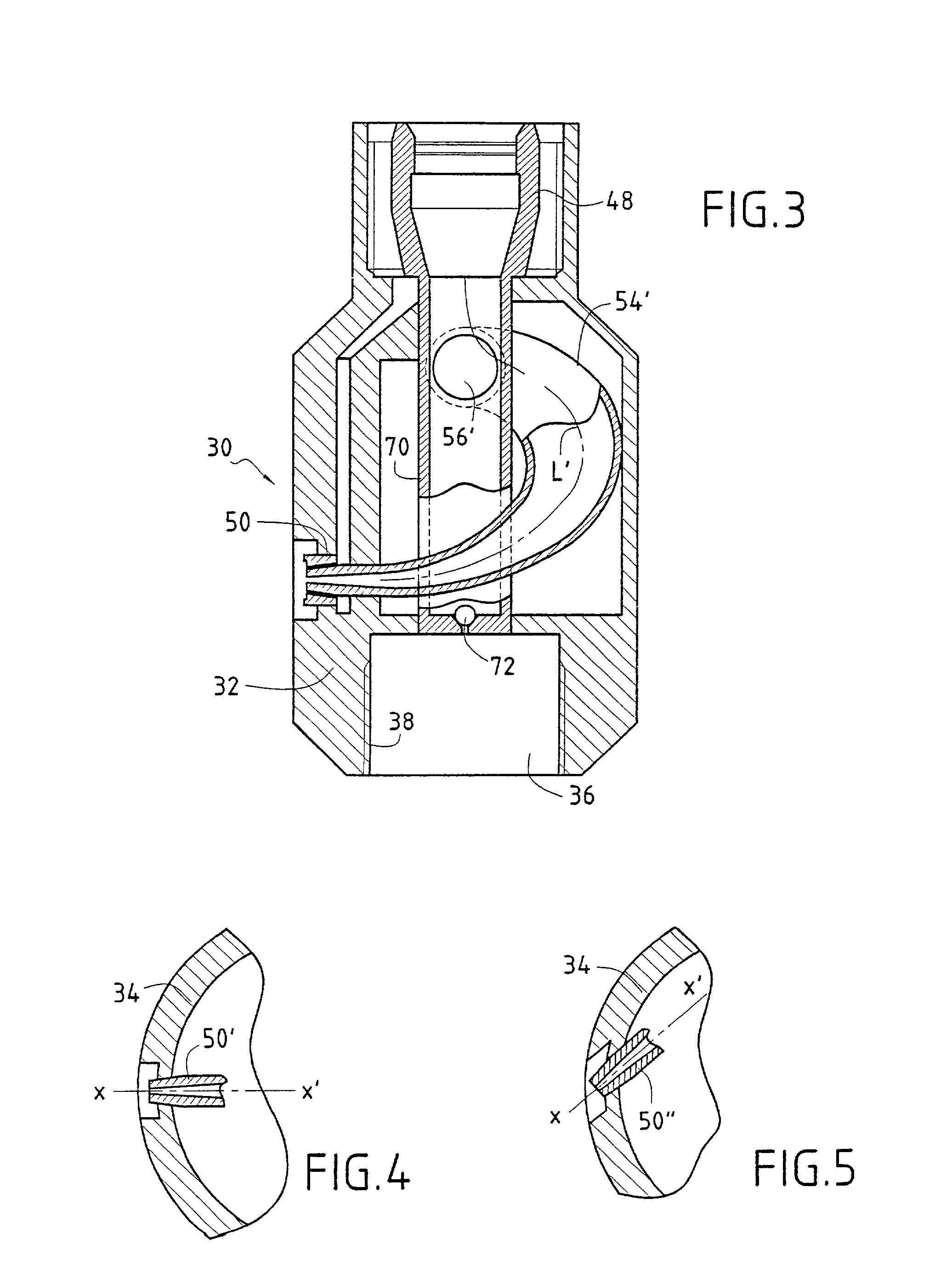
[0022] The injection head 30 shown in FIG. 2 comprises a body 32 constituted by a cylindrical side wall 34, a bottom end 36 including means, e.g. a thread 38, for securing a mechanical boring tool, and a top end 40. The top end 40 carries both a thread 42 for connection to the bottom end of a drill string 44 and an inside sleeve 46 for connection to the pipe 48 provided inside the drill string 44 for conveying pressurized liquid which is generally constituted by a slurry, as mentioned above. In the particular embodiment described, the annular space 50 between the drill string 44 and the pipe 48 is used to convey air under pressure. Naturally, in certain embodiments, it is possible to omit this annular space.

[0023] Above its bottom end 36, the side wall 34 of the injection head is provided with an injection nozzle 50 on axis x,x'. In the embodiment described, the axis x,x' of the nozzle 50 is substantially perpendicular to the vertical axis z,z', of the injection head, however in oth...


PUM


Abstract

The invention provides a head for injecting a liquid under pressure from a borehole to break up the soil, said head being mounted at the end of a drill string including liquid feed means for feeding a liquid under pressure. The head comprises a body and an outside wall, the body having at least one injection nozzle mounted therein, the nozzle having an inlet diameter equal to d and presenting an axis x,x', the body also having duct-forming means. The duct-forming means present a mean line having a first end connected to the bottom end of the liquid feed means and having a second end connected to the nozzle tangentially to the axis x,x'. The mean line is defined by at least one curved portion presenting a radius of curvature that varies continuously. The right section of the duct-forming means decreases regularly over at least half of its length from its first end to its second end.

Description

[0001] The present invention relates to a head for injecting liquid under pressure to excavate the ground, and in particular it relates to an injection head for implementing the technique known as "jet grouting".[0002] The jet grouting technique consists in breaking up the soil by means of a jet of liquid having very high kinetic energy that is implemented in a borehole, the liquid jet serving to erode the ground in which excavation is to be performed. To form the jet, a nozzle is used which is fixed to the end of a drill string, the rods of the drill string serving simultaneously to convey liquid under high pressure to the nozzle(s) and to move the nozzle progressively in translation in the soil. More precisely, the nozzle(s) is / are mounted on a member usually referred to as a "monitor" or as an "injection head", which member is fixed to the bottom end of the drill string, said monitor itself optionally being fitted at its bottom end with a mechanical boring tool. As is known, the ...

Claims


Application Information

Patent Timeline
Patent Type & Authority Applications(United States)
IPC IPC(8): E02D3/12
CPCE02D3/12
Inventor MOREY, JACQUESGESSAY, JEAN-CLAUDE
Owner CIE DU SOL
Why Eureka
Try Eureka