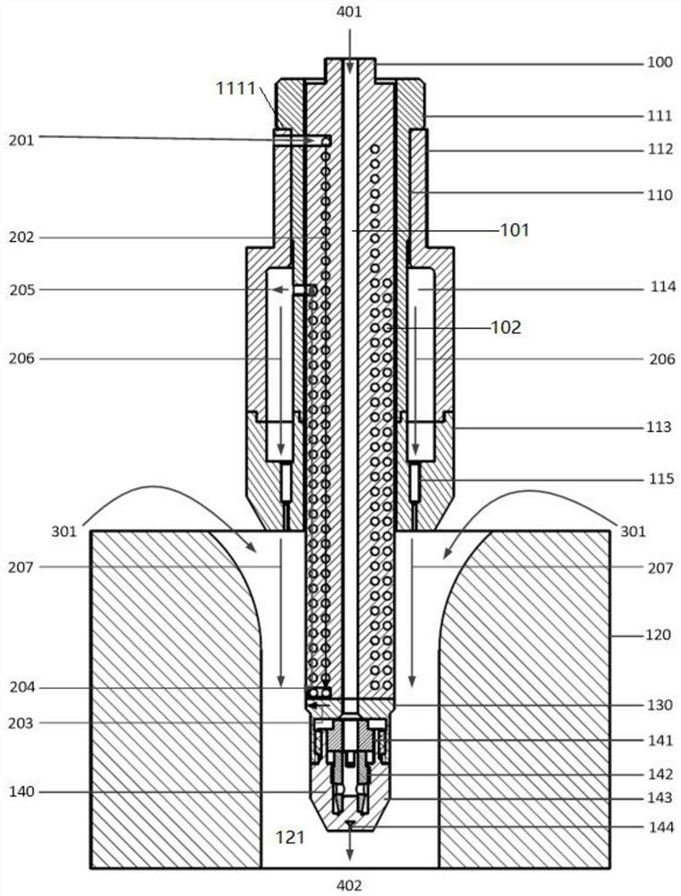
An anti-carbon fuel injection device

A fuel injection and carbon deposition prevention technology, applied in fuel injection devices, special fuel injection devices, charging systems, etc., can solve the problems of clogging fuel nozzles and clogging, and achieve the goal of avoiding carbon deposition, reducing use costs, and avoiding waste. Effect

Active Publication Date: 2022-06-07
SHANGHAI MICROPOWERS
View PDF0 Cites 0 Cited by
  • Summary
  • Abstract
  • Description
  • Claims
  • Application Information

AI Technical Summary

Problems solved by technology

On the one hand, the high temperature causes the fuel inside the flow channel to decompose, resulting in coking and carbon deposits, which block the fine swirl grooves on the swirl body; on the other hand, on the outer surface of the fuel injection device, the incompletely burned fuel will Generate carbon deposits and block fuel injectors

Method used


Image

  • An anti-carbon fuel injection device

Examples


Embodiment Construction

[0042] In order to more clearly describe the embodiments of the present invention or the technical solutions in the prior art, the specific embodiments of the present invention will be described below with reference to the accompanying drawings. Obviously, the accompanying drawings in the following description are only some embodiments of the present invention. For those of ordinary skill in the art, other drawings can also be obtained from these drawings without creative efforts, and obtain other implementations.

[0043] For the sake of brevity of the drawings, only the parts related to the present invention are schematically shown in the drawings, and they do not represent the actual structure as a product. In addition, in order to make the drawings concise and easy to understand, in some drawings, only one of the components having the same structure or function is schematically shown, or only one of them is marked. As used herein, "one" not only means "only one", but also "...


PUM


Abstract

The invention discloses an anti-carbon fuel injection device, which comprises: a fuel injection mechanism and an oxidant injection mechanism; the fuel injection mechanism includes a fuel pipe and a fuel nozzle assembly; The injection section installed on the side; the fuel injection nozzle assembly is installed at the end of the injection section away from the fuel inlet section; the fuel that flows through the oil inlet section and the high temperature end in turn and is injected by the fuel injection nozzle assembly is injected by the oxidizer injection mechanism The oxidant and high-temperature flue gas are mixed in the mixing channel of the mixing tube and then flow to the combustion chamber; the injection section extends into the mixing channel; the side wall of the injection section is provided with a channel for circulating cooling fluid. The present invention performs heat exchange between the cooling fluid and the oil pipe, and further realizes the cooling of the fuel oil in the fuel passage of the oil pipe to reduce the generation of carbon deposits, thereby reducing the carbon deposits in the fuel passages, improving the quality of fuel injection, and preventing the fuel nozzle assembly from being deposited by carbon The blockage will affect the working performance of the engine.

Description

technical field [0001] The invention relates to the technical field of fuel injection devices for engines, in particular to a carbon deposition prevention fuel injection device. Background technique [0002] Fuel injection devices are widely used in internal combustion engines, gas turbines, Stirling engines and oil-fired boilers. They are the core components of such thermal energy equipment and directly affect the performance and efficiency of the equipment. If it is damaged, it can lead to shutdown in serious cases. . In continuous combustion equipment such as boilers, gas turbines and Stirling engines, in order to improve the spray quality, pressure atomized fuel injection devices, also known as centrifugal fuel injection devices, are generally used. This type of injection device has an independent swirl fluid inside, and the fuel will rotate when passing through the small swirl groove outside the swirl fluid to improve the atomization quality. [0003] In Stirling engi...

Claims


Application Information

Patent Timeline
Patent Type & Authority Patents(China)
IPC IPC(8): F02M53/08F02M53/04F02M57/04
CPCF02M53/08F02M53/043F02M57/04F02M2200/06
Inventor 王圳兰健吕田刘佳伟顾根香
Owner SHANGHAI MICROPOWERS
Why Eureka
Try Eureka