Resonator device, filter, duplexer, and communication apparatus using the same

a technology of resonator and duplexer, which is applied in the direction of resonators, electrical devices, waveguides, etc., can solve the problem of enlargement of the entire filter

Inactive Publication Date: 2003-07-24
MURATA MFG CO LTD
View PDF2 Cites 14 Cited by
  • Summary
  • Abstract
  • Description
  • Claims
  • Application Information

AI Technical Summary

Problems solved by technology

On the other hand, when the number of stages of resonators is increased in a filter using a semi-coaxial resonator, a number of additional resonators equivalent to the number of increased stages are needed, with the result that the entire filter becomes larger.

Method used


Image

  • Resonator device, filter, duplexer, and communication apparatus using the same
  • Resonator device, filter, duplexer, and communication apparatus using the same
  • Resonator device, filter, duplexer, and communication apparatus using the same

Examples


first embodiment

[0047] With reference to FIGS. 1 to 5, a description will be given of the structure of a resonator device according to the present invention.

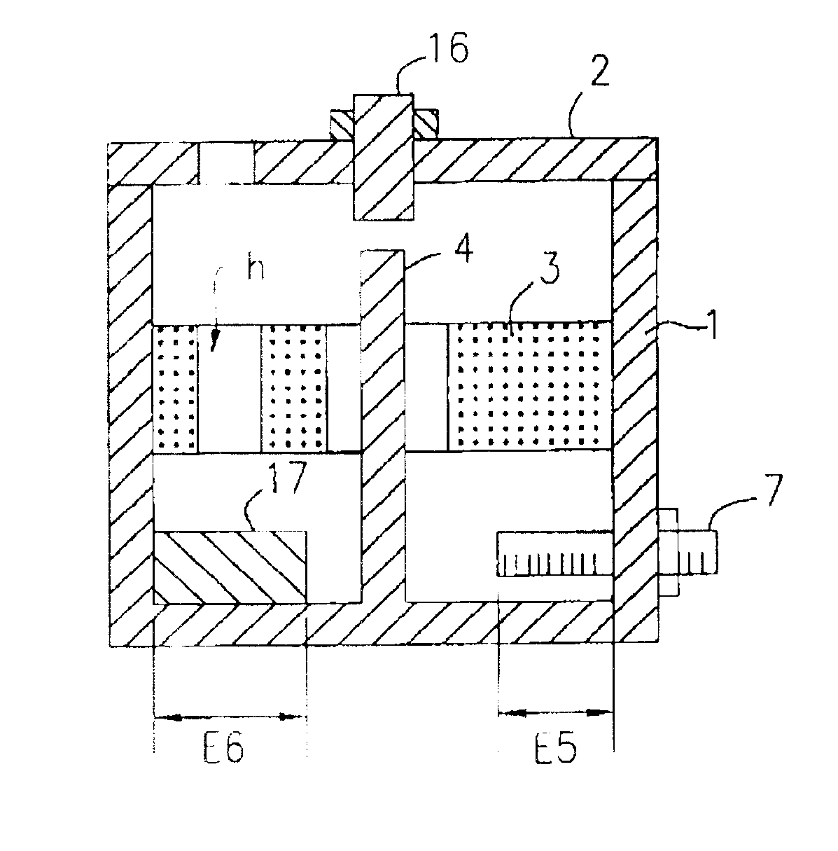
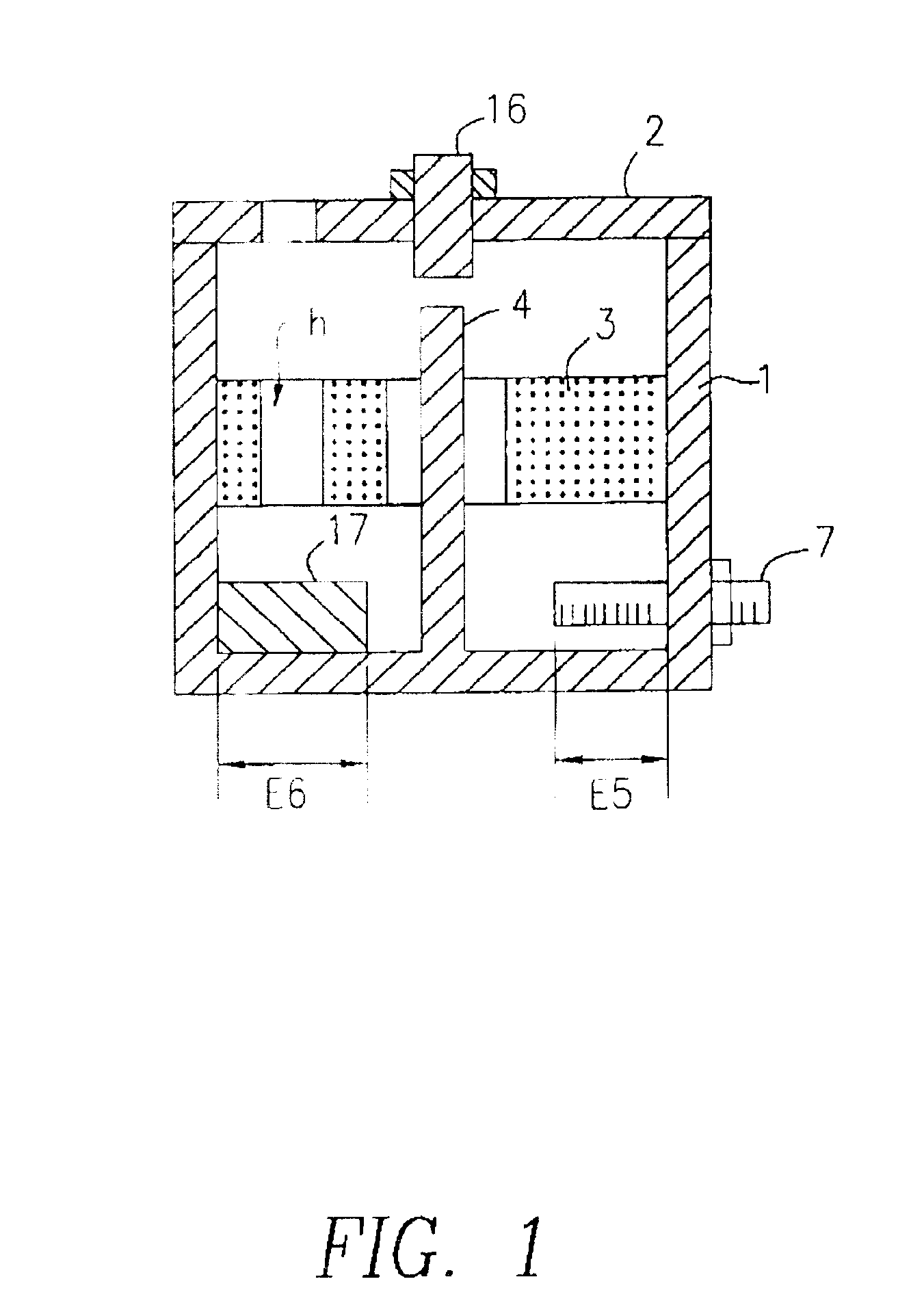
[0048] FIG. 1 is a section showing the structure of a dual-mode resonator. In FIG. 1, reference numeral 2 denotes a cover for covering the opening part of a cavity 1. At the center of the cavity's cover 2, a frequency adjusting screw 16 is disposed to adjust a resonant frequency by setting a predetermined distance between the top end of a conductive rod 4 and the inner surface of the cover.

[0049] Both end faces of the lengthwise direction of a dielectric core 3 are bonded with the inner wall surfaces of the cavity 1. In this example, an Ag electrode is formed on each of the end faces of the dielectric core 3 and the end faces are connected to the inner wall surfaces of the cavity 1 by soldering in such a manner that the dielectric core 3 is positioned at the center of the space inside the cavity. The cavity 1 and the cover 2 are formed by cutti...

second embodiment

[0061] Next, as the present invention, a resonator device having three resonators will be described with reference to FIGS. 6A to 6D to FIGS. 9A and 9B.

[0062] Each of FIGS. 6A and 6C is a perspective view of a resonator device using triplex resonance modes obtained by summing a TM dual mode and a TEM mode. In each of the figures, reference numeral 1 denotes a cavity and the inner surfaces of the cavity 1 are outlined by two-dot chain lines. A dielectric core 3 is formed by arranging two prism-shaped dielectric cores perpendicular to each other to make a configuration in the shape of a cross. At the center of the dielectric core 3, a cylindrical hole is formed and a conductive rod 4 is inserted therein.

[0063] In the example shown in FIG. 6A, as in the case of coupling between the single TM mode and the single TEM mode shown in FIGS. 3A to 3D, in this case, with a TMx mode and a TEM mode as two coupling modes, a coupling adjusting block 17 is disposed at a place where the magnetic fie...

third embodiment

[0073] Next, a filter according to the present invention will be described with reference to FIG. 10.

[0074] In FIG. 10, each of reference characters RWa and RWb denotes a dual-mode resonator using a TM mode and a TEM mode. The basic structure of each resonator device is the same as that shown in FIG. 1 and FIGS. 2A to 2C. Reference numerals 8a and 8b denote coaxial connectors, and the central conductors of the coaxial connectors are connected to coupling loops 9a and 9b. A coupling loop 10ab is coupled with the TEM-mode magnetic fields of the dual-mode resonators RWa and RWb. As a result, the two TEM modes couple with each other via the coupling loop 10ab. The coupling adjusting blocks 17a and 17b provide coupling between the TM modes and the TEM modes of the dual-mode resonators RWa and RWb. Coupling adjusting holes ha and hb are provided for adjusting the couplings between the TM modes and the TEM modes of the dual-mode resonators RWa and RWb. By inserting a dielectric rod in each...


PUM


Abstract

A multi-mode resonator device can be reduced in size even while increasing the number of resonators while including either a semi-coaxial resonator or a coaxial resonator. Coupling between a TEM mode as a resonance mode of the semi-coaxial resonator and a TM mode as another resonance mode can be facilitated, which enables coupling between the resonators at a predetermined coupling strength. Inside a cavity with a cover, a conductive rod and a dielectric core are disposed so as to substantially equalize a quasi-TEM-mode resonant frequency generated by the cavity and the conductive rod and a quasi-TM-mode resonant frequency generated by the cavity and the dielectric core. A coupling adjusting block is arranged at a place where the magnetic field of one of two coupling modes generated by the quasi-TEM and quasi-TM modes is strong and that of the other mode is weak. The invention also provides a filter, duplexer, and a communication apparatus using the resonator device.

Description

[0001] 1. Field of the Invention[0002] The present invention relates to a resonator device including a plurality of resonators, a filter, a duplexer, and a communication apparatus using the resonator device.[0003] 2. Description of the Related Art[0004] Publicly known resonators capable of handling a relatively large amount of power in a microwave band include cavity resonators and semi-coaxial resonators. A semi-coaxial resonator is also referred to as a coaxial cavity resonator. It has a relatively high Q factor, and is smaller than a cavity resonator. Accordingly, the use of semi-coaxial resonators contributes to the miniaturization of filters and the like.[0005] However, for example, in a cellular mobile communication system such as a mobile phone system, with the spread of micro-cellular networks, there has been a growing demand for more compact filters for use in base stations.[0006] On the other hand, when the number of stages of resonators is increased in a filter using a se...

Claims


Application Information

Patent Timeline
Patent Type & Authority Applications(United States)
IPC IPC(8): H01P1/205H01P1/208H01P1/213H01P7/04H01P7/06H01P7/10
CPCH01P1/2053H01P1/2084H01P7/105H01P7/04H01P1/2086
Inventor SAITO, KENJIWAKAMATSU, HIROKIISE, TOMOYUKI
Owner MURATA MFG CO LTD
Why Eureka
Try Eureka