Toilet assembly

Inactive Publication Date: 2004-03-04
AS IP HOLDCO LLC
View PDF6 Cites 24 Cited by
  • Summary
  • Abstract
  • Description
  • Claims
  • Application Information

AI Technical Summary

Benefits of technology

0014] Therefore, it is an advantage of the present invention to provide

Problems solved by technology

In the past, toilet designs have attempted by various methods to comply with this reduced water requirement, but achieving superior flush performance has been difficult.
However, the hydraulic energy available is not enhanced by the typical rim wash employed in existing toilets as the water path flows in two opposite directions through the rim of the toilet thus reducing the available energy.
All of the tested designs shared some of the same problems, but in varying degrees.
First, several of the models had clogging problems.
In most of these toilets, this problem could be attributed to an undersized trapway.
Second, when there was a sig

Method used


Image

  • Toilet assembly
  • Toilet assembly
  • Toilet assembly

Examples


Example

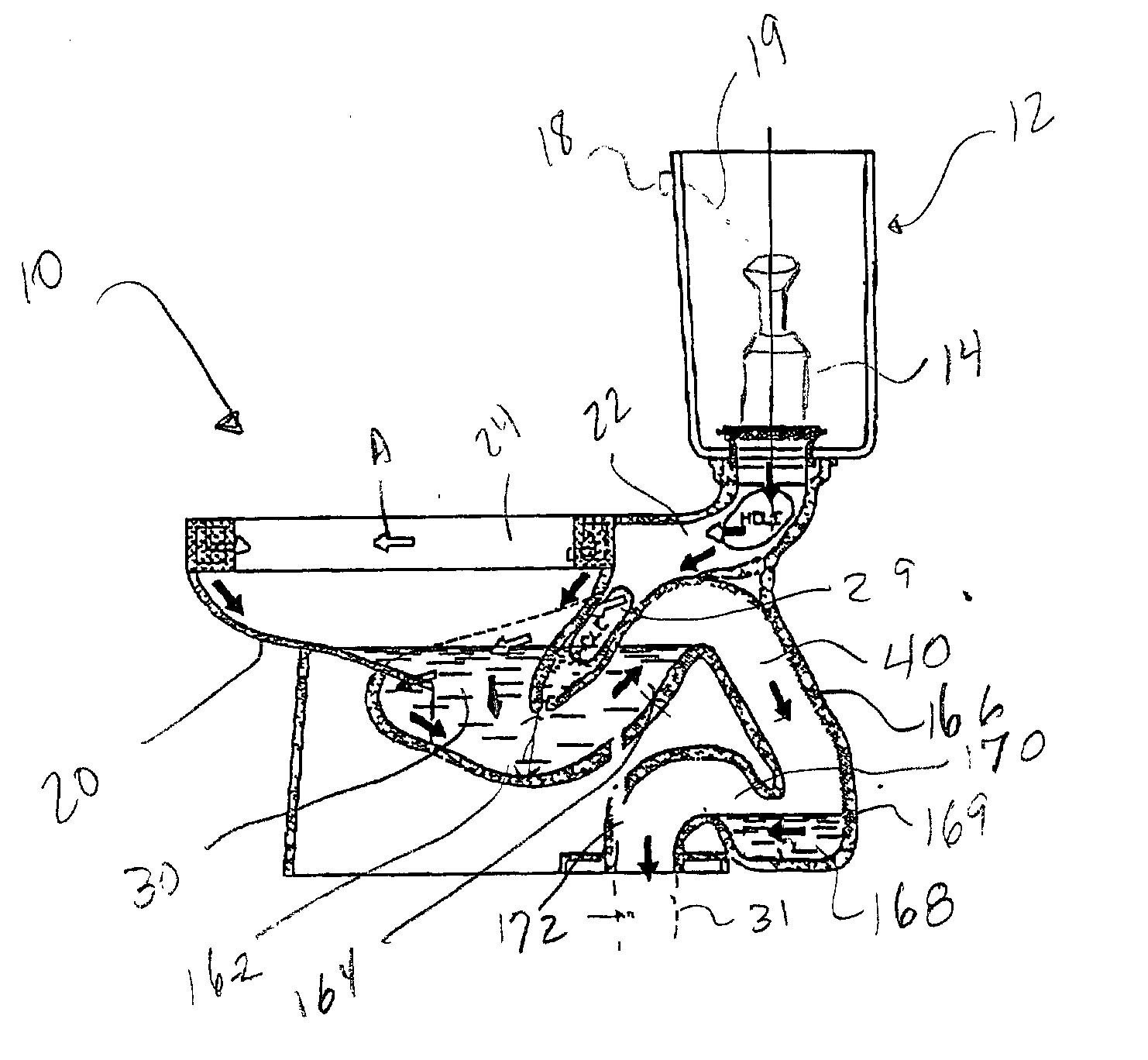
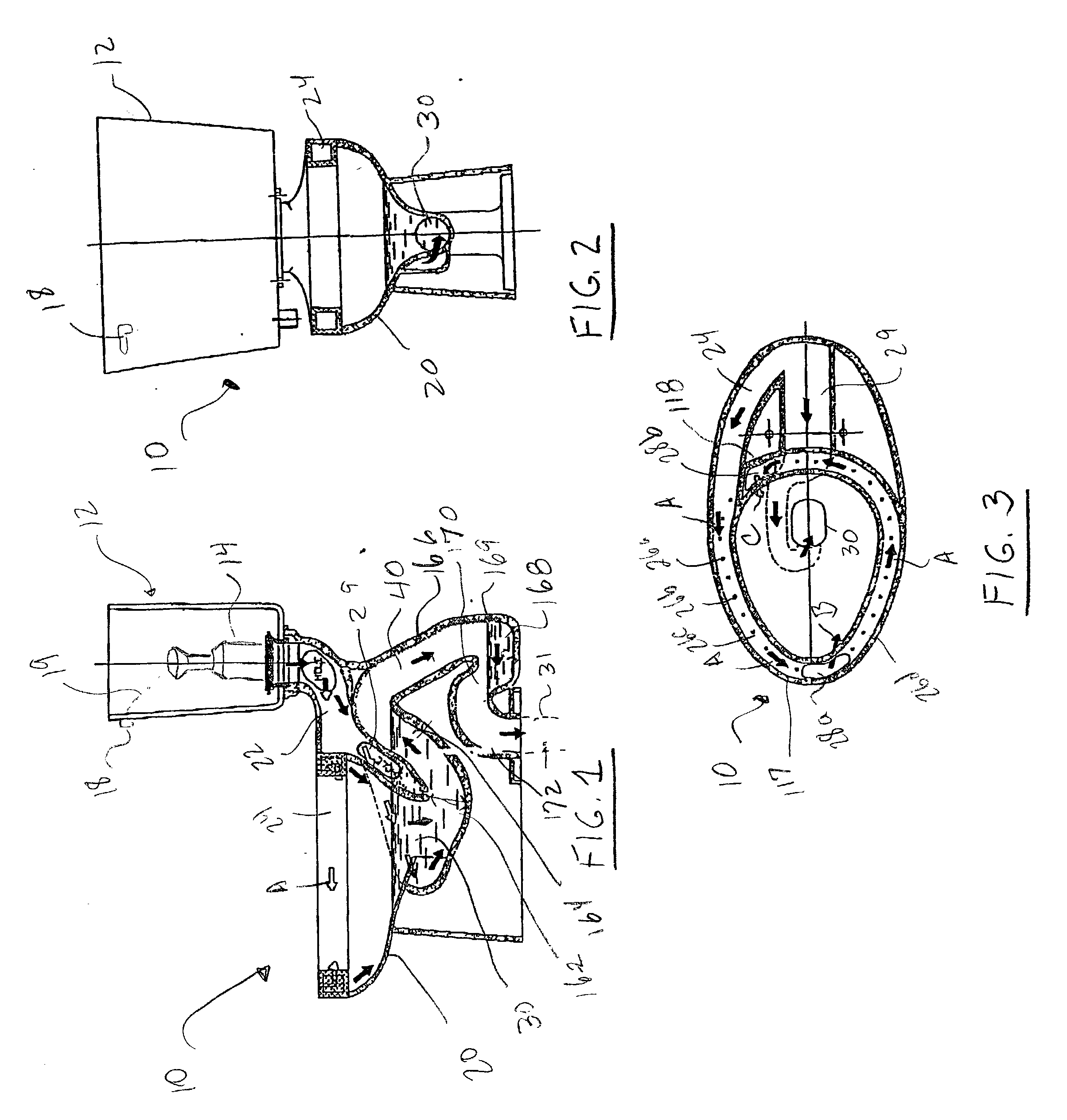
[0059] Referring now to FIGS. 1-3, a toilet tank in accordance with the teachings of the present 15 invention is illustrated. As will be explained in more detail below, this toilet has a greater energy throughput of the flush water to thereby provide more energy available to remove waste from the toilet bowl. In addition, this toilet permits a toilet to meet governmental agency requirements which mandate a maximum water usage of 1.6 gallons (6 liters) per flush. Further, this toilet improves the flow characteristics of the flow water and flow capacity to provide for not only a more efficient flush but also enhanced cleaning performance and anti-clogging siphoning to assist in waste removal. Moreover, this toilet provides for a quieter and faster flush operation.

[0060] As shown in FIGS. 1-3, the toilet 10 includes a water tank 12 which includes a flush valve assembly 14. The water tank 12, which is positioned over the back of the toilet bowl 20, contains water that is used to initiat...


PUM


Abstract

A toilet includes a toilet bowl assembly having a toilet bowl and a trapway extending from the bottom of the toilet bowl to a sewage line. The toilet bowl has a rim channel provided along an upper perimeter portion thereof. In this toilet, the flush water flows through the rim channel in a path which is asymmetric and unidirectional along the entire perimeter portion thereof. The rim channel includes a plurality of rim openings distributed evenly along the perimeter of the rim channel. Flush water passing through the plurality of rim openings pre-wets the entire perimeter of the toilet bowl. The rim channel further includes a pair of water discharge slots which directs water directly into the toilet bowl in two powerful streams. The flush valve allowing passage of water from the water tank to the toilet bowl assembly is in the form of a valve inlet having a radiused port to generate greater energy throughput of the flush water.

Description

[0001] The present invention relates to a toilet for the removal of human and other waste. The present invention further relates to a toilet which is resistant to clogging, increases flushing capacity, and delivers the flush water volume with greater energy.BACKGROUND OF INVENTION[0002] Toilets for removing waste products are well known. Typically, toilets incorporate three systems that work together to perform the flushing action. Those systems are (1) the bowl siphon, (2) the flush mechanism, and (3) the refill mechanism. Working in concert, these three systems allow for the flushing function of the toilet.[0003] Siphoning is used to transport fluid and waste from the higher elevation of the bowl to a lower elevation of the wastewater line. The flow channels in a toilet assembly are designed to begin siphoning when the water in the bowl rises above a certain level. The siphon tube itself is an upside down U-shaped tube that draws water from the toilet bowl to the wastewater line. ...

Claims


Application Information

Patent Timeline
IPC IPC(8): E03D1/34E03D11/08
CPCE03D1/34E03D2201/40E03D2201/30E03D11/08
Inventor HAN, JOSEPH UNKYUNGPROKOPENKO, ALEKSANDR V.JENSEN, ROBERT MICHAEL
Owner AS IP HOLDCO LLC
Why Eureka
Try Eureka