Device for mixing fluids

Inactive Publication Date: 2004-03-25
ROBERT BOSCH GMBH
View PDF6 Cites 9 Cited by
  • Summary
  • Abstract
  • Description
  • Claims
  • Application Information

AI Technical Summary

Problems solved by technology

Often, the problem arises that the steam delivered condenses inside the nozzle or inside the nozzle valve, causing it to freeze and thus become

Method used


Image

  • Device for mixing fluids
  • Device for mixing fluids
  • Device for mixing fluids

Examples


Embodiment Construction

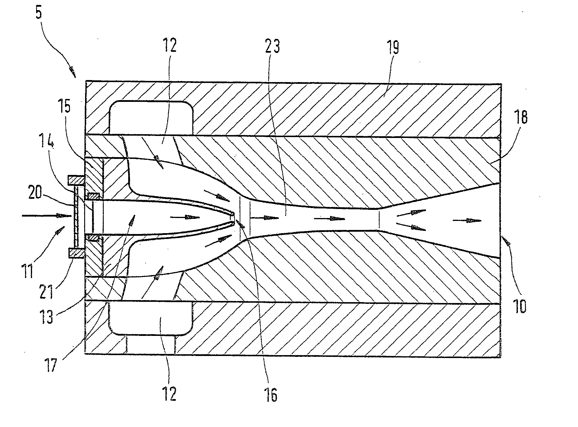
[0020] FIG. 1 shows a fluid mixing device 5, which is embodied as a gas injection valve or mixing nozzle. In particular, the fluid mixing device 5 is a jet compression nozzle, in which a strong propelling flow through the nozzle drags another, weaker flow along with it. For instance, in the fluid mixing device 5 described, hydrogen and saturated steam are mixed with one another in a mixing tube or mixing region inside the mixing device 5.

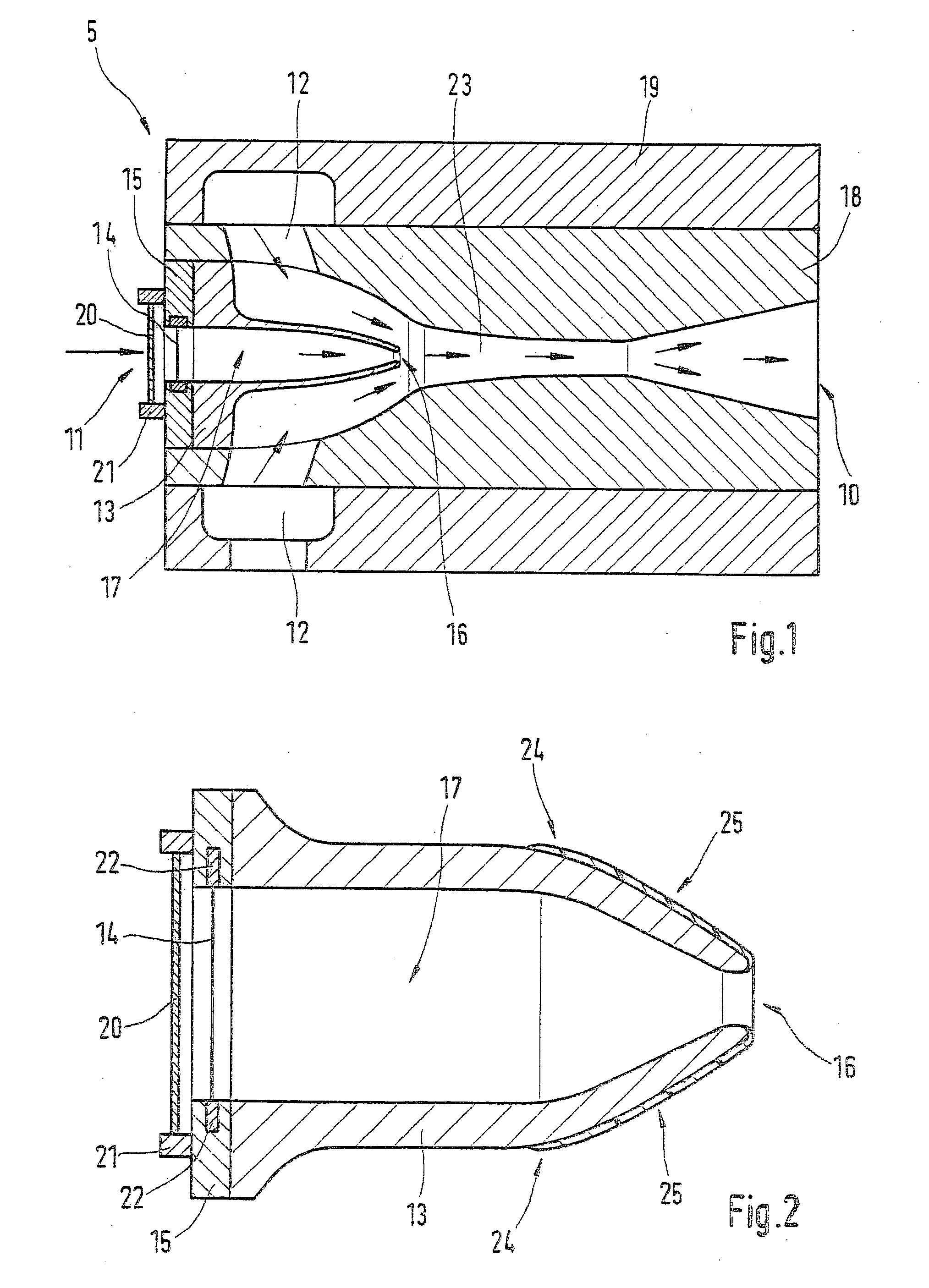
[0021] For that purpose, the fluid mixing device 5 has a base body 18, which is surrounded by a sleeve 19 with an annular conduit, by way of which a first fluid, such as hydrogen or a gas containing hydrogen, can be delivered to the base body 18. Also provided in the base body 18 is a funnel-shaped recess, which discharges into a central conduit 23 that leads to an outlet 15 of the fluid mixing device 5 that widens in funnel-like fashion. The sleeve 19 or base body 18 of FIG. 1 is preferably embodied cylindrically symmetrically.

[0022] FIG. 1 also sh...


PUM


Abstract

A device for mixing fluids, in particular a gas injection valve, nozzle valve, mixing nozzle or jet compressor, is proposed. To that end, a first fluid-carrying device (12) for carrying a first fluid and a second fluid-carrying device (13) for carrying a second fluid are provided; the fluids are mixed with one another in a mixing region (16) that is in communication with the fluid-carrying devices (12, 13). In addition, a means (20) for generating turbulence in the applicable fluid and a heater, with which the fluid can be heated before reaching the mixing region (16), disposed downstream of the means (20) for generating turbulence in terms of the flow direction of the applicable fluid are associated with at least one of the fluid-carrying devices (12, 13). The proposed device is used in particular for mixing hydrogen and saturated steam and to deliver this mixture to a fuel cell.

Description

[0001] The invention relates to a device for mixing fluids, in particular a gas injection valve, mixing nozzle or jet compression nozzle, for instance for use to deliver fuel to a fuel cell, as generically defined by the preamble to the main claim.PRIOR ART[0002] In the operation of fuel cells, it is known to supply them with a mixture of hydrogen and saturated steam; the mixture quantity of hydrogen and saturated steam, and its composition, are metered in or adjusted via a nozzle valve.[0003] Often, the problem arises that the steam delivered condenses inside the nozzle or inside the nozzle valve, causing it to freeze and thus become plugged, or causing failure in the function of the nozzle and the downstream fuel cell, or a marked reduction in the efficiency of the nozzle.[0004] The object of the present invention was to furnish a device for mixing fluids, in particular for mixing hydrogen and in particular saturated steam, that can also be used to deliver fuel to a fuel cell, in ...

Claims


Application Information

Patent Timeline
IPC IPC(8): B65B57/18B65B57/02B67B1/00B67B3/26F23D11/40F23D11/44F23D14/64F23D14/66F23M5/02G06T1/00H01M8/04007H01M8/04089H01M8/04119
CPCB01F5/0413Y02E60/50B01F5/0473B01F15/066B01F2005/0025B01F2005/0048B01F2015/062F23D11/402F23D11/44F23D14/64F23D14/66F23M5/025H01M8/04007H01M8/04089H01M8/04119B01F5/0428Y02E20/34B01F2025/916B01F2025/919121B01F25/31242B01F25/3141B01F25/312B01F35/93B01F2035/99
Inventor FAYE, IANNGUYEN-SCHAEFER, THANH-HUNG
Owner ROBERT BOSCH GMBH
Why Eureka
Try Eureka