Method and apparatus for improving the comfort of CPAP

Active Publication Date: 2005-01-13
RESMED LTD
View PDF34 Cites 113 Cited by
  • Summary
  • Abstract
  • Description
  • Claims
  • Application Information

AI Technical Summary

Benefits of technology

[0021] In accordance with one aspect of the invention there is provided a low-cost CPAP apparat

Problems solved by technology

A mismatch between the device control cycle and the patient respiratory cycle can lead to patient discomfort.
To achieve this change, the peak power load may be in the order of 60-90 W. Because of the low inertia and peak load requirements of the VPAP® device, a large and expensive power supply is required.
The shape of the waveform actually delivered to the patient may be affected by the compliance and resistance of the patient's respiratory system and his brea

Method used


Image

  • Method and apparatus for improving the comfort of CPAP
  • Method and apparatus for improving the comfort of CPAP
  • Method and apparatus for improving the comfort of CPAP

Examples


Embodiment Construction

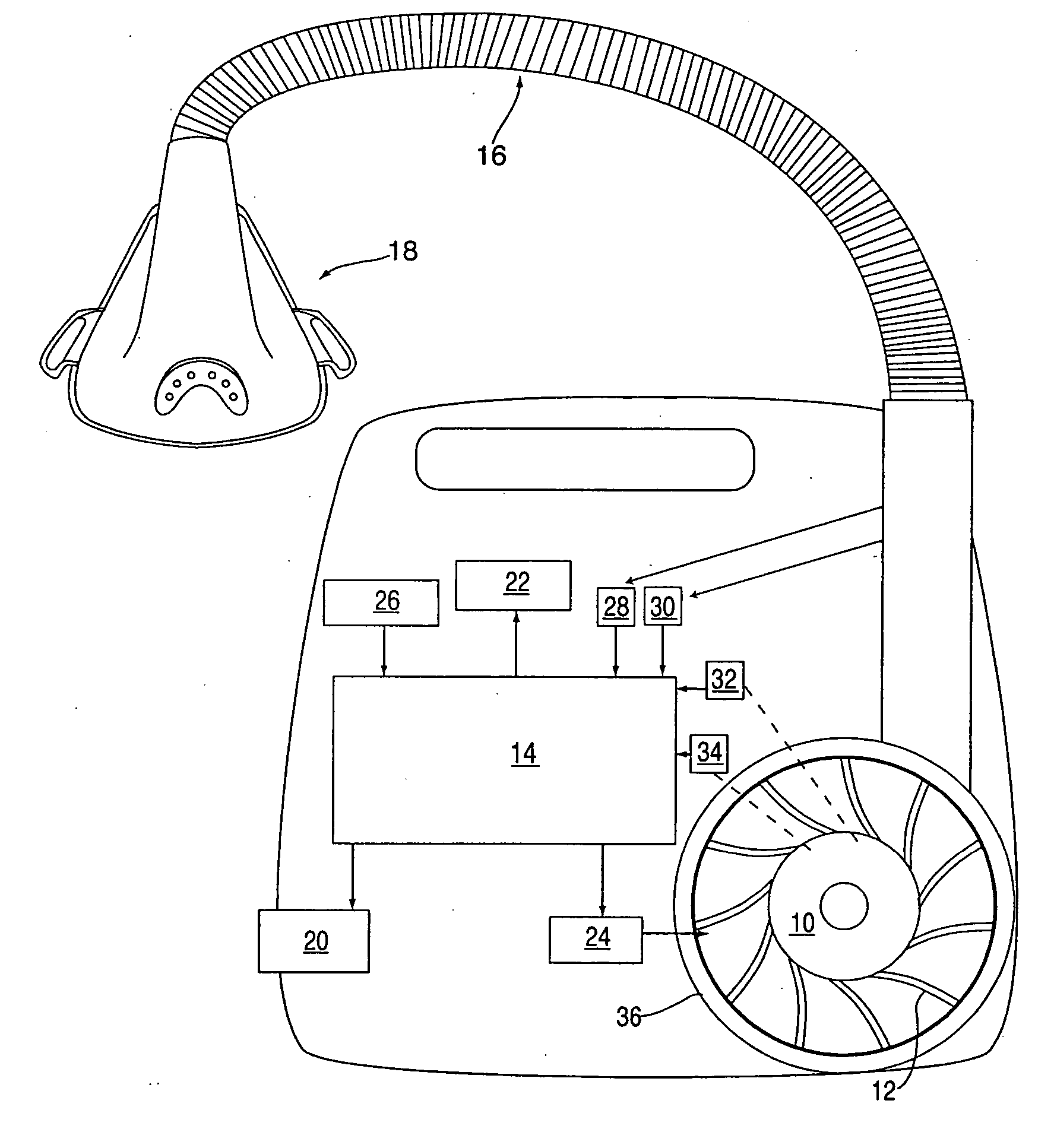
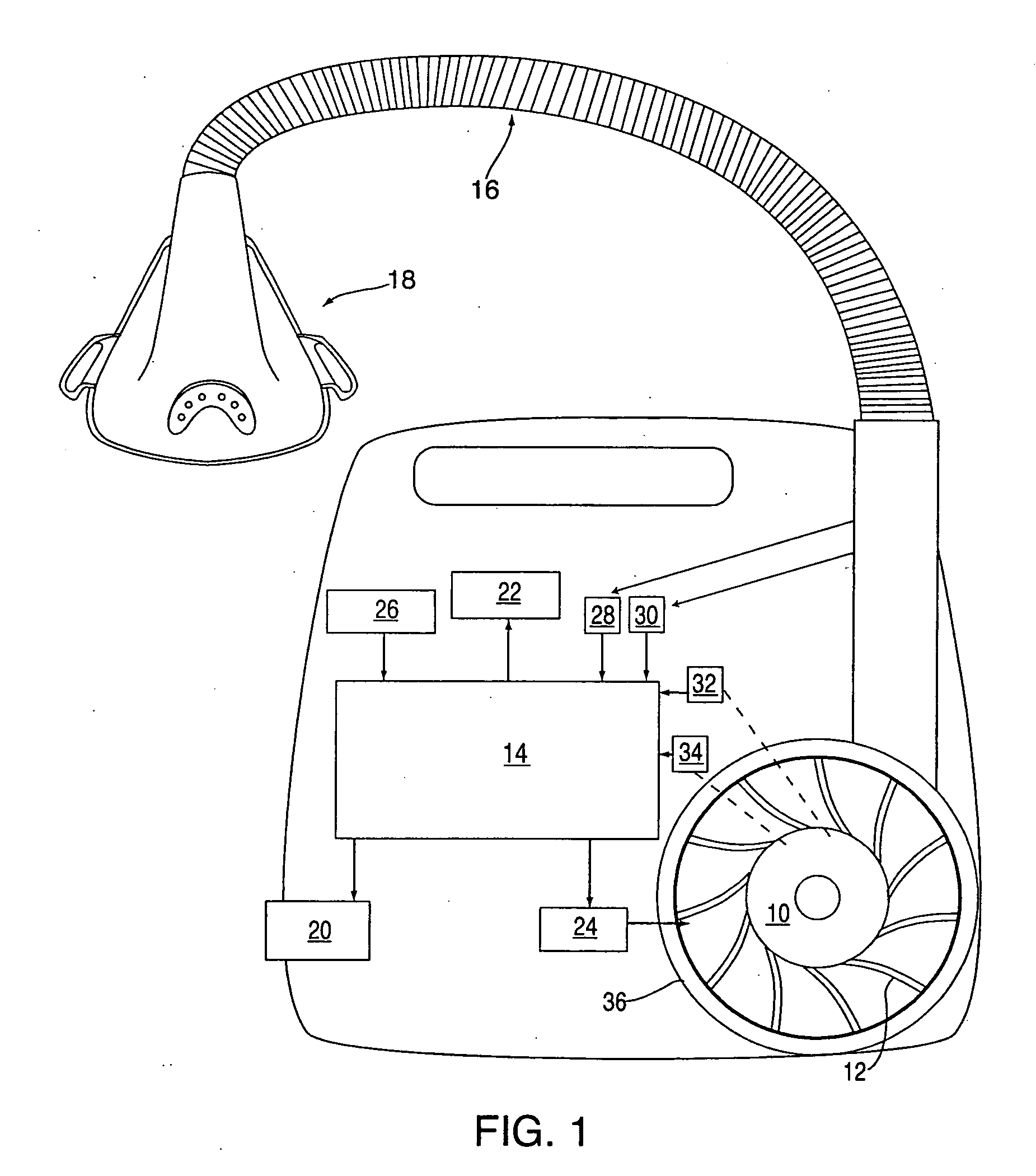
[0048]FIG. 1 shows apparatus in accordance with an embodiment of our invention. A brushless electric motor 10 has an impeller 12 attached to it. The impeller 12 resides in a volute 36. The motor 10 is under the control of a motor controller 24 (suitable controllers include TMS320LC2402 or MC33035 IC). The motor includes sensors 32, 34 that provide signals indicative of motor rotational speed and current respectively. When the windings of the motor are energized, the impeller rotates. Air is drawn in through the inlet of the impeller and gains momentum. As the air passes out of the impeller and into the volute, it changes speed and develops pressure. Air passes out of the volute, past flow and pressure sensors 28, 30 (such as SM15652-003 flow sensor and SMI5652-008 or MPX2010 pressure sensors) respectively to an air delivery conduit 16 (for example, manufactured by Smooth-bor Plastics) that is in turn connected to a patient interface 18 which in the illustrated embodiment is a nasal ...


PUM


Abstract

A low-cost CPAP apparatus in which, upon detection of the transition from inhalation to exhalation, the blower motor is de-energized to allow it to freewheel. When the pressure in the patient mask (or whatever interface is utilized) reaches a minimum pressure level during exhalation, the motor is re-energized and its speed is controlled so to maintain the pressure at a level suitable for exhalation. Upon detection of the transition from exhalation to inhalation, the motor speed is increased to provide higher pressures in the patient mask suitable for inhalation.

Description

[0001] This application claims the foreign priority of Australian provisional application No. AU 2003903138 filed on Jun. 20, 2003. FIELD OF THE INVENTION [0002] The invention relates to a method and apparatus for delivering a supply of air at positive pressure to a patient for treating sleep disordered breathing. In particular, the invention relates to a method and apparatus which provides a smooth, comfortable pressure versus time waveform. BACKGROUND OF THE INVENTION [0003] Since the invention of nasal Continuous Positive Airway Pressure (nasal CPAP) for treatment of Obstructive Sleep Apnea (OSA) and other forms of Sleep Disordered Breathing (SDB) by Sullivan, as taught in U.S. Pat. No. 4,944,310, much effort has been directed towards improving the comfort of the devices. One aspect of this is a more comfortable patient interface, such as provided by the MIRAGE® and ULTRA MIRAGE® masks manufactured by ResMed Limited. Another aspect of providing a more comfortable patient interfac...

Claims


Application Information

Patent Timeline
IPC IPC(8): A61B5/08A61HA61M16/00
CPCA61B5/08A61M2205/3334A61M16/0051A61M2016/0021A61M2016/0027A61M2016/0036A61M2205/3365A61M2205/3553A61M2205/3584A61M2205/502A61M2230/63A61M16/0069A61M16/0003A61M16/06A61M16/0666A61M2016/0018A61B5/417A61M16/026A61M16/022A61M16/024A61M16/021
Inventor FARRUGIA, STEVEN PAULALDER, MATTHEWPRICE, ANDREW MARTINRICHARD, RON
Owner RESMED LTD
Why Eureka
Try Eureka