

Liquid-discharge-head recovering device
a liquid discharge and recovery device technology, applied in printing and other directions, can solve the problems of large amount of ink left on the discharging surface, improper discharging of liquid, and liquid spattering of the liquid remaining on the wiper blade used so as to prevent the thickening of the liquid remaining on the wiper blade during the wiping process and the effect of minimizing liquid spatter
- Summary
- Abstract
- Description
- Claims
- Application Information
AI Technical Summary
Benefits of technology
Problems solved by technology
Method used
Image



Examples
first embodiment
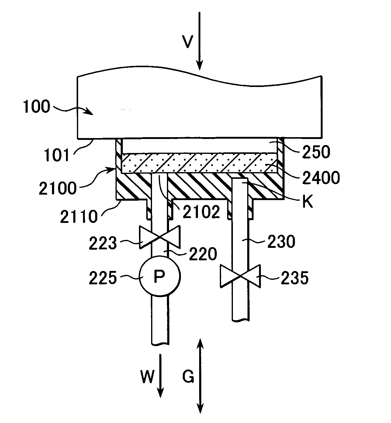
[0035]FIG. 1 is a schematic perspective view of an inkjet printer 15 which includes a liquid-discharge-head recovering device 5 provided with a liquid-discharge-head cap 2100 according to one of the embodiments of the present invention. FIG. 2 is a schematic perspective view of the recovering device 5 in FIG. 1. FIG. 3 is a schematic plan view of the cap 2100 according to the present invention. FIG. 4 is a cross-sectional view of the recovering device 5 including the cap 2100 taken along line IV-IV in FIG. 3. FIG. 5 is a cross-sectional view of the recovering device 5 including the cap 2100 taken along line V-V in FIG. 3.
[0036] The inkjet printer 15 in FIG. 1 is provided with a feeder 1 for feeding a recording medium, such as paper, to a recording position; a sender 2 for pulling the recording medium from the feeder 1; a liquid discharge head (an ink-jet print head) 100 functioning as a printing element; a carriage 4 which carries the discharge head 100 and moves horizontally with r...
second embodiment
[0060]FIG. 6 is a schematic plan view of the liquid-discharge-head cap 2100 according to the present invention. FIG. 7 is a cross-sectional view of the recovering device 5 including the cap 2100 taken along line VII-VII in FIG. 6. FIG. 8 is a cross-sectional view of the recovering device 5 including the cap 2100 taken along line VIII-VIII in FIG. 6. FIG. 9 is a cross-sectional view of the recovering device 5 including the cap 2100 taken along line IX-IX in FIG. 6.
[0061] Referring to FIGS. 6 to 9, similar to the first embodiment, the cap 2100 of the second embodiment is formed of an elastic material, such as rubber, and has the substantially rectangular base 2110 whose four corners are curved. The base 2110 is provided with the air-communication openings 2103 and 2104. Like the first embodiment, the two opposite ends of one of the shorter sides 2111 of the substantially rectangular base 2110 respectively have neighboring corners 2113 and 2114, and the openings 2103 and 2104 are dispo...
PUM
 Abstract
Description
Claims
Application Information