Spinal implant

a technology of spinal cord and implant, applied in the field of spinal cord implants, can solve the problems of destabilizing the spinal cord, pain and/or nerve damage, altering the natural separation distance between adjacent vertebrae, etc., and achieve the effect of promoting bone growth and fusion of adjacent vertebra

Active Publication Date: 2005-02-03
ZIMMER BIOMET SPINE INC
View PDF82 Cites 419 Cited by
  • Summary
  • Abstract
  • Description
  • Claims
  • Application Information

AI Technical Summary

Benefits of technology

[0009] A spinal implant may be used to provide stability and promote fusion of adjacent vertebrae. The implant may be used in conjunction with a spinal stabilization device such as a bone plate or rod-and-fastener stabilization system. The implant may establish a desired separation distance between vertebrae. The implant may promote bone growth between adjacent vertebrae that fuses the vertebrae together. An instrumentation kit may include instruments and implants necessary for insertion of an implant in a patient.

Problems solved by technology

Partial or full removal of an intervertebral disc may destabilize the spinal column.
Destabilization of a spinal column may result in alteration of a natural separation distance between adjacent vertebrae.
Excessive pressure applied to the nerves may cause pain and / or nerve damage.
Spinal surgery may be complex due in part to the proximity of the spinal cord and / or the cauda equina.

Method used


Image

  • Spinal implant
  • Spinal implant
  • Spinal implant

Examples


Embodiment Construction

[0036] An intervertebral disc implant may be used to stabilize a portion of a spine. The disc implant may replace all or a portion of an intervertebral disc that has degenerated due to natural wear, trauma, or disease. The implant may restore a normal separation distance between adjacent vertebrae and promote fusion of the vertebrae.

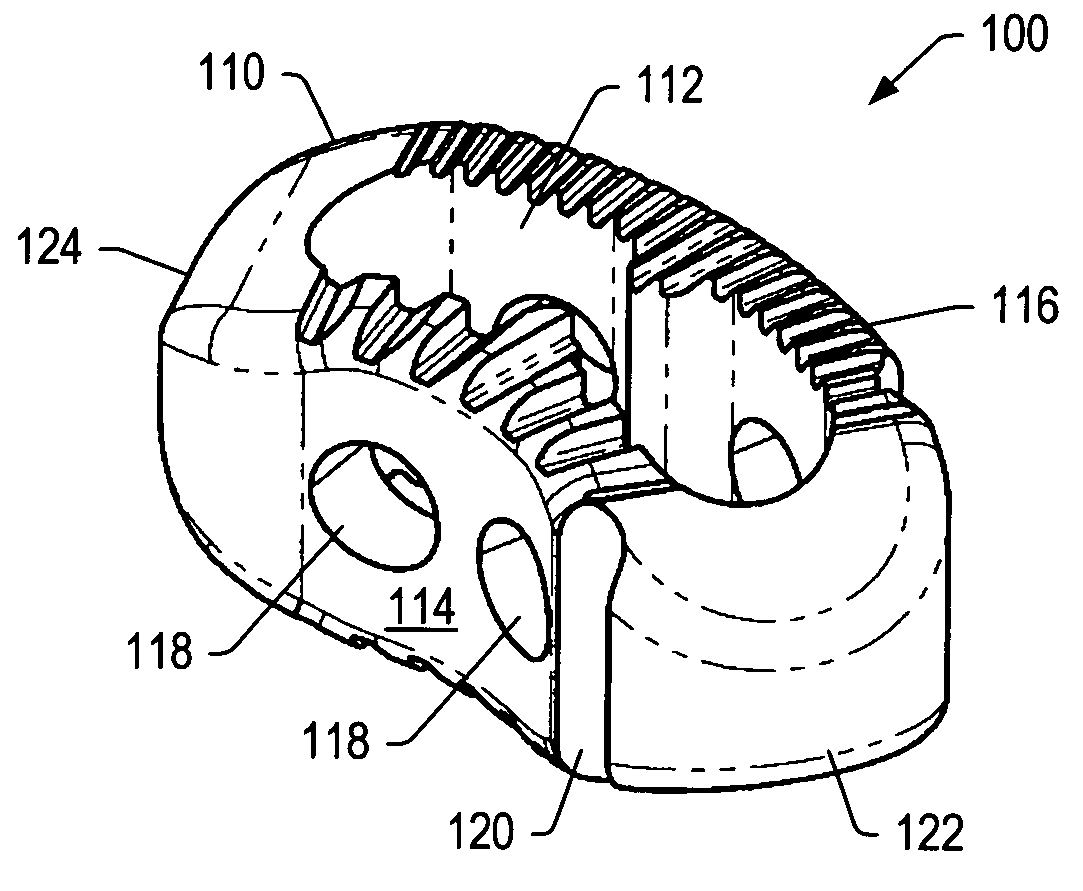
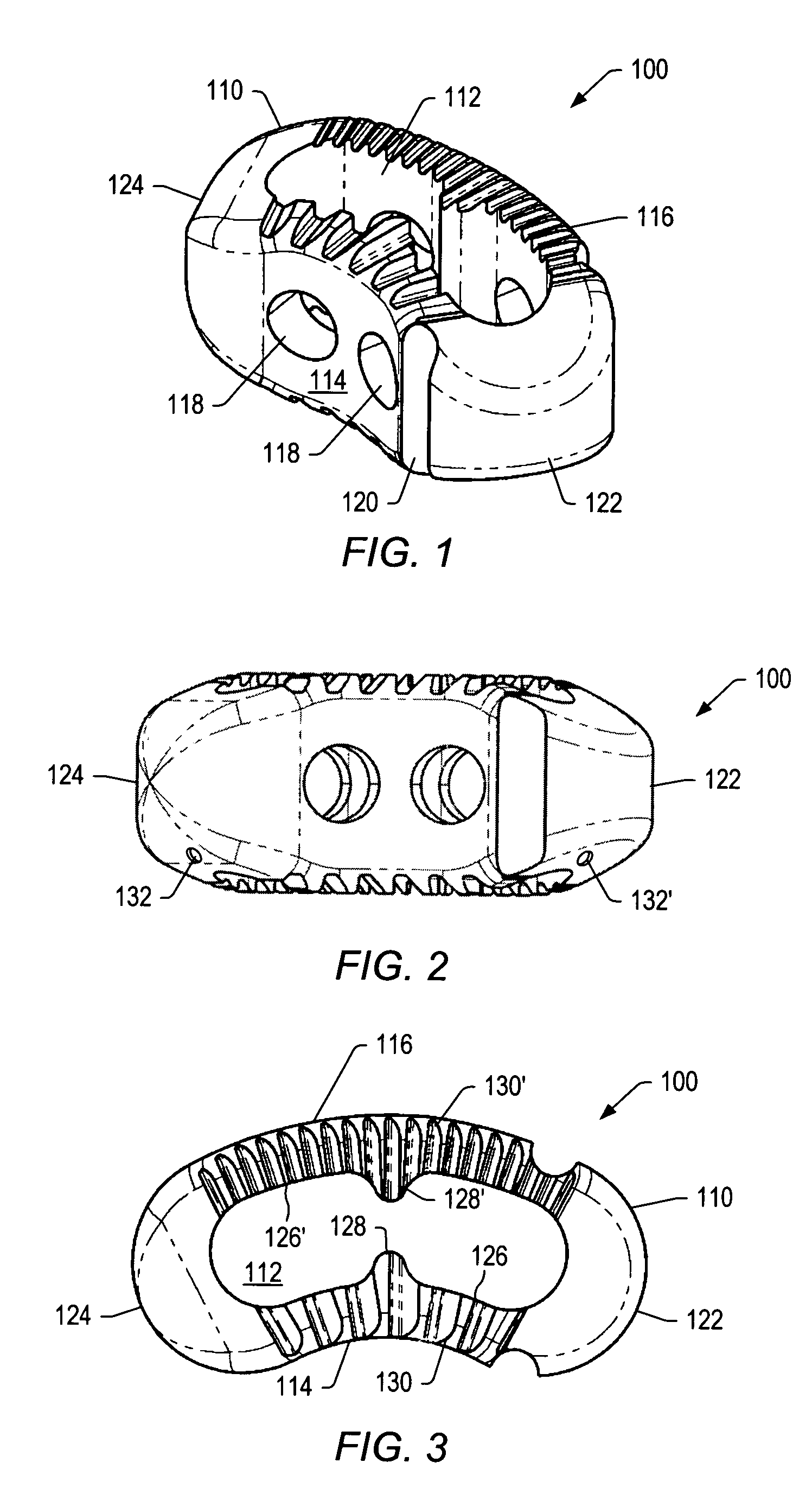
[0037]FIG. 1 depicts a perspective view of implant 100. Implant 100 may include body 110. Body 110 may include opening 112. Opening 112 may extend completely or partially through a height of body 110. A cross-sectional shape of opening 112 may be, but is not limited to, circular, oval, square, rectangular, or irregular. In certain embodiments, opening 112 may be kidney shaped.

[0038] Body 110 of implant 100 may include posterior side 114 and anterior side 116. Sides 114, 116 of implant 100 may be curved. In some embodiments, the curvature of posterior side 114 may be substantially the same as the curvature of anterior side 116. In some embodiments, the ...


PUM

PropertyMeasurementUnit
lordotic angleaaaaaaaaaa
lengthaaaaaaaaaa

Abstract

A spinal implant may be used to stabilize a portion of a spine. The implant may promote bone growth between adjacent vertebrae that fuses the vertebrae together. An implant may include an opening through a height of a body of the implant. The body of the implant may include curved sides. A top and/or a bottom of the implant may include protrusions that contact and/or engage vertebral surfaces to prevent backout of the implant from the disc space. A variety of instruments may be used to prepare a disc space and insert an implant. The instruments may include, but are not limited to, a distractor, a rasp, and one or more guides. The implant and instruments may be supplied in an instrument kit.

Description

BACKGROUND [0001] 1. Field of Invention [0002] The present invention generally relates to the field of medical devices. Some embodiments of the invention relate to spinal implants inserted in patients during surgical procedures and to instruments used to insert the implants. Some embodiments of the invention relate to instruments for preparing a space for an implant. Other embodiments of the invention relate to methods for positioning an implant during a surgical procedure. [0003] 2. Description of Related Art [0004] An intervertebral disc may degenerate. Degeneration may be caused by trauma, disease, and / or aging. An intervertebral disc that becomes degenerated may have to be partially or fully removed from a spinal column. Partial or full removal of an intervertebral disc may destabilize the spinal column. Destabilization of a spinal column may result in alteration of a natural separation distance between adjacent vertebrae. Maintaining the natural separation between vertebrae may...

Claims


Application Information

Patent Timeline
Patent Type & Authority Applications(United States)
IPC IPC(8): A61B17/02A61B17/16A61B19/00A61F2/00A61F2/02A61F2/28A61F2/30A61F2/44A61F2/46
CPCA61B17/1659A61F2310/00359A61B2017/0256A61B2019/462A61F2/28A61F2/4465A61F2/4611A61F2002/2835A61F2002/30059A61F2002/30062A61F2002/3008A61F2002/30133A61F2002/30308A61F2002/30324A61F2002/30326A61F2002/30538A61F2002/30604A61F2002/30616A61F2002/30677A61F2002/30787A61F2002/3082A61F2002/30894A61F2002/30904A61F2002/30924A61F2002/4475A61F2002/4623A61F2002/4624A61F2002/4627A61F2002/4635A61F2210/0004A61F2230/0015A61F2230/0063A61F2250/0006A61F2250/0036A61F2250/0037A61F2250/0098A61F2310/00017A61F2310/00023A61F2310/00179A61F2310/00407A61F2310/00796A61B17/1671A61B2090/062A61F2/4603A61F2002/30593A61F2002/30922
Inventor WEBB, SCOTT A.MORENO, ANTHONY P.MITCHELL, MARGARET E.SMITH, AARON C.
Owner ZIMMER BIOMET SPINE INC
Why Eureka
Try Eureka