Padlock

a technology of padlocks and locks, applied in the field of padlocks, can solve the problems of travelers losing their properties in travel baggage boxes, travelers without knowing the security number, and unable to unlock their baggage boxes,

Inactive Publication Date: 2005-02-24
CHUN TE YU & FULLYEAR BROTHER ENTERPRISE
View PDF53 Cites 65 Cited by
  • Summary
  • Abstract
  • Description
  • Claims
  • Application Information

AI Technical Summary

Benefits of technology

[0003] It is therefore an objective of the present invention to provide a padlock that can be unlocked by the owner of the padlock by dialing an unlocking number or by authorized security personals with a general key.

Problems solved by technology

Thereby others without knowing the security number cannot unlock his baggage box.
However terrorists may use travel baggage boxes to deliver explosive devices to endanger people's safety.
The travelers may lose their properties in their travel baggage boxes if they leave their travel baggage boxes unlocked.
There is a dilemma between travelers' rights and flight safety.

Method used


Image

  • Padlock
  • Padlock
  • Padlock

Examples


first embodiment

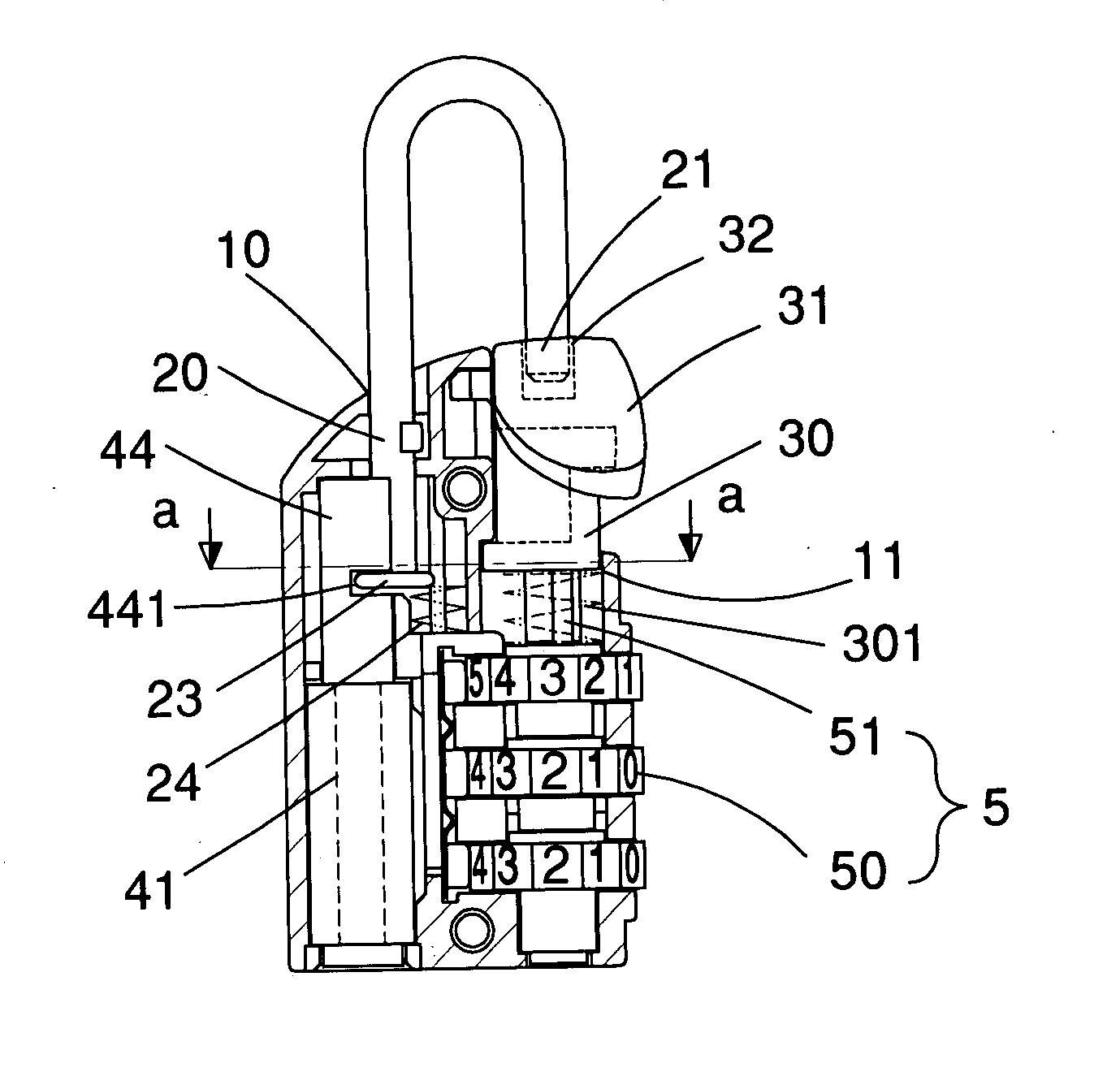
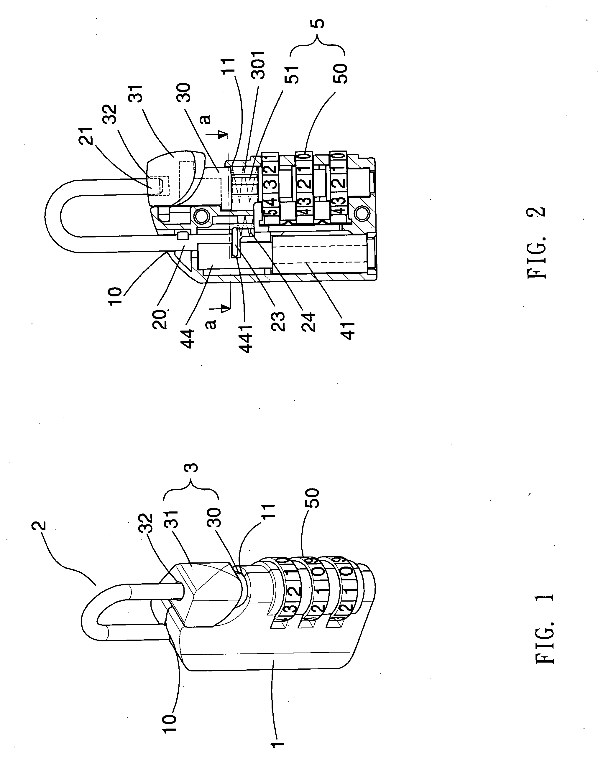
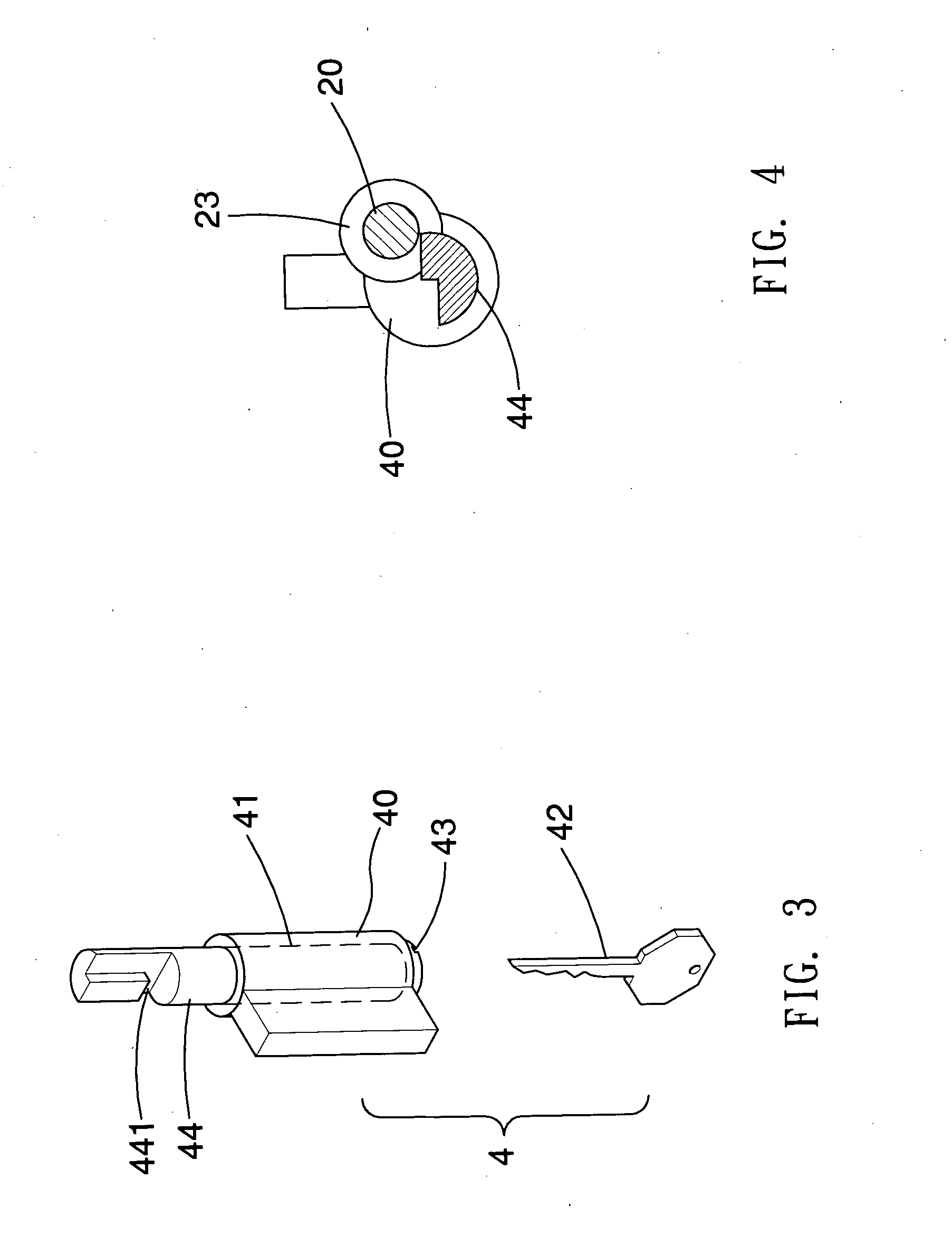
[0037] With reference to FIG. 1 and FIG. 2, the padlock of the first embodiment contains a lock body 1, a block 3, a shackle 2, a key operated locking means 4 and a combination locking means 5. The lock body 1 has a first channel 10 and a second channel 11 therein. The block 3 contains an engaging portion 31 having a receptacle 32 therein and a mounting portion 30 under the engaging portion 31. The mounting portion 30 is received in the second channel 11 of the lock body 1. The combination locking means 5 is formed in the lock body 1 for controlling movements of the block 3 in order the block 3 to be engaged with or disengaged from the shorter arm 21 of the shackle 2. The combination locking means 5 contains a stem 51 connected to the mounting portion 30 and plural number wheels 50 rotatably mounted around the stem 51 for controlling vertical movement of the block 3. Only when the number wheel is dialed to the unlocking number the stem 51 can move vertically. The engaging portion 31...

fourth embodiment

[0044] With reference to FIG. 18 to FIG. 23, the padlock of the present invention mainly contains: a lock body 70, a block 72, a shackle 71, a combination locking means 9 and a key operated locking means 8. The lock body 70 has a first channel 701 and a second channel 702 therein. The block 72 is engaged with the second channel 702. The block 72 has a receptacle 723 therein. The shackle 71 has a longer arm 711 slidably received in the first channel 701 and a shorter arm 712 engagable with the receptacle 723 of the block 72. The combination locking means 9 formed in the lock body 70 for locking or unlocking the longer arm 711 of the shackle 71. The key operated locking means 8 is formed in the lock body 70 for controlling movements of the block 72 in order the block 72 to be engaged with or disengaged from the shorter arm 712 of the shackle 71. The block 72 has a receptacle 723 therein and a gap 725 communicated with the receptacle 723 of the block 72. The gap 725 has a width larger ...

fifth embodiment

[0047] With reference to FIG. 24 to FIG. 27, the padlock of the present invention mainly contains: a lock body 70a, a block 72a, a spring 724a, a shackle 71a, a combination locking means 9a and a key operated locking means 8a. The lock body 70a has a channel 701a therein. The block 72a is pivotally received in the lock body 70a. The block 72a has a slot 723a thereon. The spring 724a is engaged with the block 72a for restoring the block 72a. The shackle 71a has a longer arm 711a slidably received in the channel 701a and a shorter arm 712a engagable with the slot 723a of the block 72a. The combination locking means 9a is formed in the lock body 70a for locking or unlocking the longer arm 711a of the shackle 71a. The key operated locking means 8a is formed in the lock body 70a for controlling rotation of the block 72a in order the block 72a to be engaged with or disengaged from the shorter arm 712a of the shackle 71a. The block 72a has a protrusion 721a thereon. The key operated lockin...


PUM


Abstract

A padlock that can be unlocked by the owner of the padlock by dialing an unlocking number or by authorized security personals with a general key. The padlock mainly contains a lock body, a block, a shackle, a general locking means and a private locking means. The lock body has a first channel and a second channel therein. The block is engaged with the second channel. The block has a receptacle therein. The shackle has a longer arm slidably received in the first channel and a shorter arm engagable with the receptacle of the block. The general locking means is formed in the lock body for locking or unlocking the longer arm of the shackle. The private locking means is formed in the lock body for controlling movements of the block in order the block to be engaged with or disengaged from the shorter arm of the shackle.

Description

TECHNICAL FIELD [0001] This invention relates generally to a padlock, in particular, to provide a padlock having a shackle locked by a key operated locking means at one end and a combination locking means at another end, thereby the padlock can be unlocked by using a key or by dialing the combination locking means to an unlocking number. BACKGROUND OF THE INVENTION [0002] Preventing personal stuffs from being lost or stolen, travelers usually lock their own travel baggage boxes. Combination lock is the most common lock that installed in a travel baggage box because it takes little space. Each traveler sets up his own security number for the combination lock. Thereby others without knowing the security number cannot unlock his baggage box. However terrorists may use travel baggage boxes to deliver explosive devices to endanger people's safety. Security personals in airports may need to exam travels' travel baggage boxes in some circumstances without presence of the owners of the trav...

Claims


Application Information

Patent Timeline
Patent Type & Authority Applications(United States)
IPC IPC(8): E05B37/00E05B37/02E05B37/20
CPCE05B35/105E05B67/18E05B37/025E05B37/0034Y10T70/7706Y10T70/415Y10T70/459Y10T70/424Y10T70/7147Y10T70/461Y10T70/7141Y10T70/463
Inventor YU, CHUN TE
Owner CHUN TE YU & FULLYEAR BROTHER ENTERPRISE
Why Eureka
Try Eureka