Mounted imaging apparatus
a technology of mounted imaging and equipment, which is applied in the direction of television systems, instruments, printers, etc., can solve the problems of slow positioning operation, missed shutter chance, and difficult for photographers to perform other operations
- Summary
- Abstract
- Description
- Claims
- Application Information
AI Technical Summary
Benefits of technology
Problems solved by technology
Method used
Image

Examples
first embodiment
[0055]FIG. 4 shows the camera shake compensating mechanism of the mounted imaging apparatus of the first embodiment in the present invention.
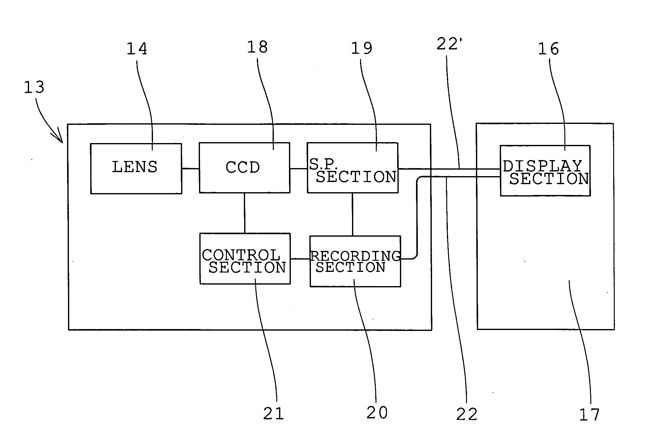
[0056] In the camera shake compensating mechanism of the first embodiment, when the photographer pushes the shutter button 15, a piezoelectric element 23 converts the pressure of the finger into an electric signal, which is transmitted to the control section 21. Here, in order to prevent the camera shake, the control section 21 is constructed so that the shutter is operated in about 0.1-1 sec after the release of the finger from the shutter button 15, and image information of the object imaged during the shutter operation is stored in the recording section (not shown).
[0057] If the shutter is operated in less than 0.1 sec after the release of the finger from the shutter button 15, the pressure of the finger still remains in the frame and the camera shake may be caused. On the other hand, if the shutter is operated in more than 1 sec after the...
second embodiment
[0059]FIG. 5 shows the camera shake compensating mechanism of the mounted imaging apparatus of the second embodiment in the present invention.
[0060] The camera shake compensating mechanism of the second embodiment is provided with two shutter buttons 24 arranged so that they can be pushed from both sides with fingers of one hand. Specifically, this mechanism is such that the photographer is capable of pushing the two shutter buttons 24 at the same time from opposite directions. The control section 21 is constructed so that when forces of the fingers pushing the two shutter buttons 24 are balanced, the shutter is operated and image information of the object imaged during the shutter operation is stored in the recording section (not shown).
[0061] According to the camera shake compensating mechanism of the second embodiment, the magnitudes and directions of forces experienced by the shutter buttons 24 pushed from both sides are detected by piezoelectric elements 25 provided on both s...
third embodiment
[0062]FIG. 6 shows the camera shake compensating mechanism of the mounted imaging apparatus of the third embodiment in the present invention.
[0063] In the camera shake compensating mechanism of the third embodiment, a shutter button 26 is connected with the imaging device 13 by a cord-like matter. Thus, a signal produced when the photographer pushes the shutter button 26 is transmitted as the electric signal to the control section 21 by a piezoelectric element 27. In this case, the camera shake compensating mechanism is such that the force of the finger pushing the shutter button 26 is not exerted on the body of the imaging device 13.
[0064] Also, it is desirable that the camera shake compensating mechanism is constructed so that the shutter button 26 is connected to the top of a short string- or spring-like cord extending from the body of the imaging device 13, and when the shutter button 26 is pushed, the force of the finger pushing the button is not exerted on the body of the im...
PUM
 Abstract
Description
Claims
Application Information
 - R&D Engineer
- R&D Manager
- IP Professional
- Industry Leading Data Capabilities
- Powerful AI technology
- Patent DNA Extraction
Browse by: Latest US Patents, China's latest patents, Technical Efficacy Thesaurus, Application Domain, Technology Topic.
© 2024 PatSnap. All rights reserved.Legal|Privacy policy|Modern Slavery Act Transparency Statement|Sitemap