Check patentability & draft patents in minutes with Patsnap Eureka AI!

Burner mechanism for a rotary kiln

a rotary kiln and burner technology, which is applied in the direction of burners, furnace types, furnaces, etc., can solve the problems of short high mechanical abrasives and thermo/chemical wear, and interruption of the whole cement clinker production line, so as to prolong the lifetime of burner lances

Inactive Publication Date: 2005-05-12
KHD HUMBOLDT WEDAG GMBH
View PDF4 Cites 0 Cited by
  • Summary
  • Abstract
  • Description
  • Claims
  • Application Information

AI Technical Summary

Benefits of technology

The burner protection shield significantly extends the lifetime of the burner lance to up to a year, allowing continuous production line operation by protecting it from abrasive and thermal stresses.

Problems solved by technology

Therefore the kiln outlet housing, and especially the burner lance, is exposed to a high mechanical abrasive and thermo / chemical wear.
There are cases where the lifetime of a burner lance is extremely short, even if the burner lance is coated with heat resistance material and has a cooling system.
An exchange or replacement of the burner lance requires interruption of the kiln operation and consequently an interruption of the whole cement clinker production line.

Method used


Image

  • Burner mechanism for a rotary kiln
  • Burner mechanism for a rotary kiln
  • Burner mechanism for a rotary kiln

Examples


Embodiment Construction

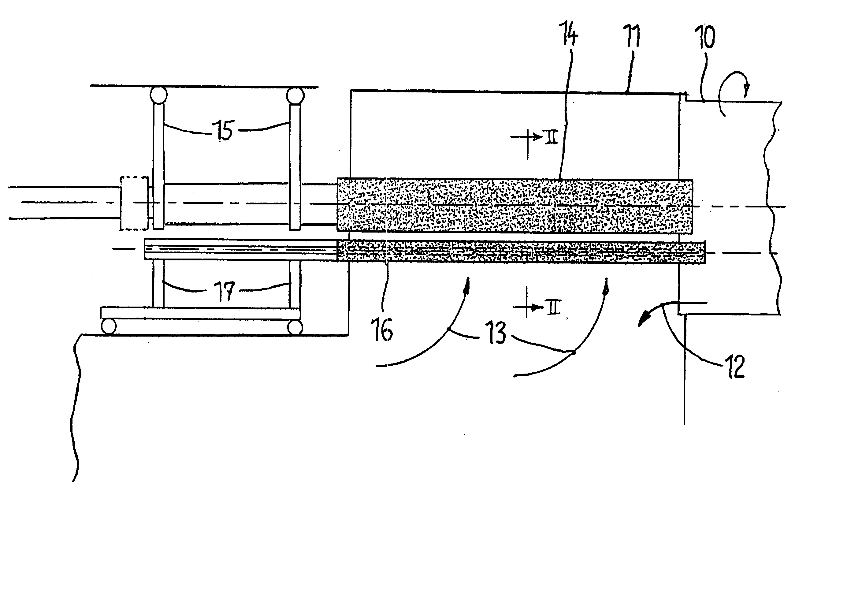
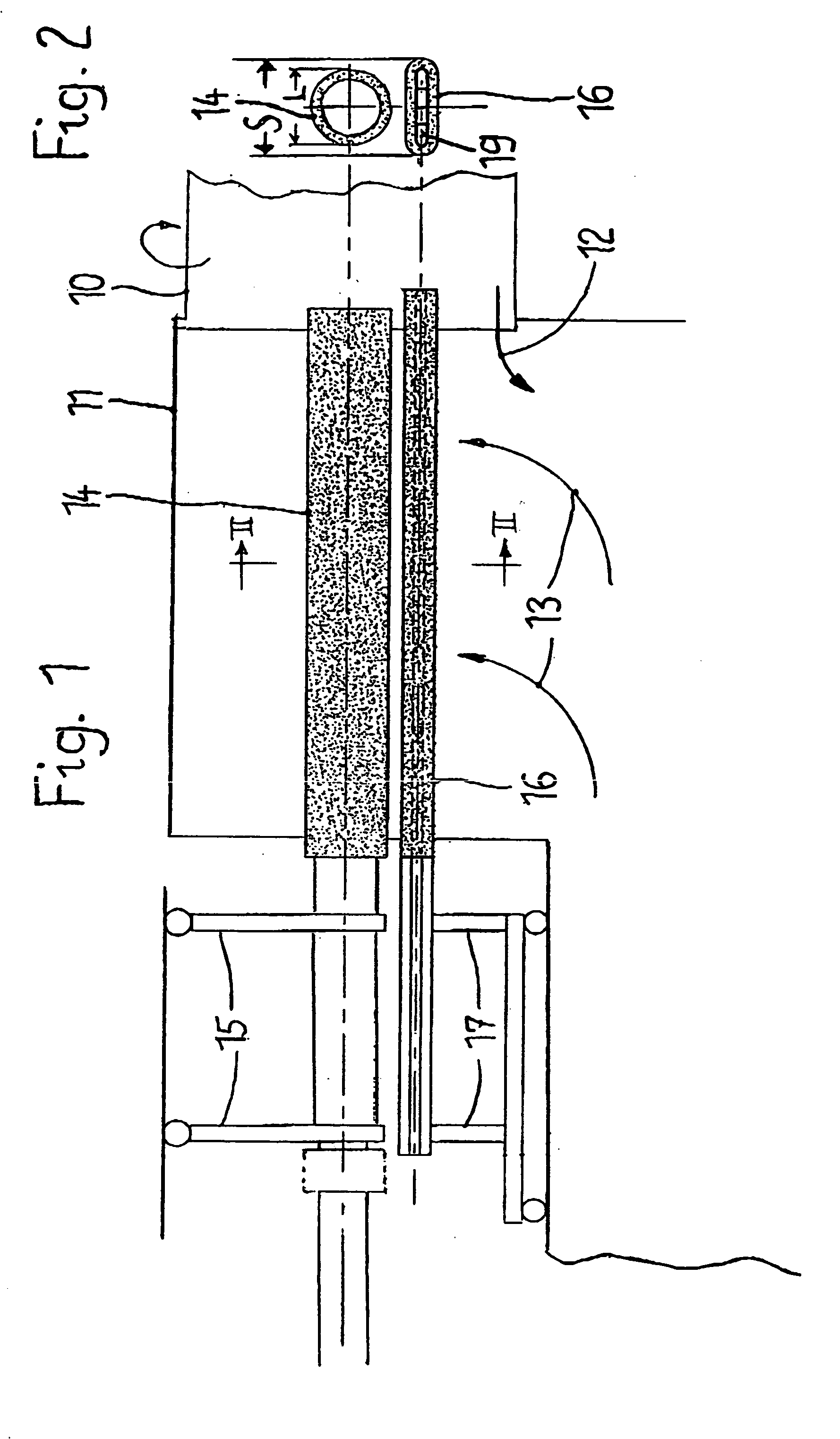
[0015] In FIG. 1, an outlet end of a rotary kiln (10) of a cement clinker production line is surrounded by a stationary kiln outlet housing (11). A complete system for manufacturing cement clinker is shown and described in U.S. Pat. Nos. 6,626,662; 6,254,382 and 6,444,026, the disclosures of which are incorporated herein by reference. From the kiln outlet the red hot cement clinker (12) falls through the kiln outlet housing (11) down to the not shown clinker cooler. From the clinker cooler, hot cooler air laden with clinker dust flows as secondary air (13) through the stationary kiln outlet housing (11) into the rotary kiln (10). The rotary kiln (10) will be heated by a flame coming out of a burner lance (14) which extends through the outlet housing (11) into the kiln end. The burner lance can be moved in the axial direction with a movable carriage (15) mounted on rollers.

[0016] Positioned at a distance below and parallel to the burner lance (14) is an exchangeable (removable and r...


PUM


Abstract

A burner protection shield is provided at a distance and in an area below a burner lance that is used in a rotary kiln for the production of cement clinker. Such a mechanism enhances the useful lifetime of the burner lance.

Description

BACKGROUND OF THE INVENTION [0001] The invention involves a burner mechanism for a rotary kiln for the production of cement clinker from raw meal, with a burner lance movable in an axial direction, which extends through the stationary kiln outlet housing into the rotary kiln end. [0002] At standard cement clinker production lines, calcined raw meal is burnt to cement clinker in the sintering zone of a rotary kiln by means of a burner lance extended through the kiln outlet housing creating a flame by means of fuel combustion. The red hot cement clinker is discharged through the kiln outlet housing onto a clinker cooler, in most cases grate coolers, and will be cooled down. In modern cement clinker production lines, the hot cooler air collected in the kiln outlet housing is utilized twofold. First, the hot air used as secondary air for the kiln firing and second, as tertiary air for a secondary firing system in the calciner stage installed according to the material flow upstream of th...

Claims


Application Information

Patent Timeline
Patent Type & Authority Applications(United States)
IPC IPC(8): F24J3/00F27B7/00F27B7/34F27D99/00
CPCF27D99/0033F27B7/34
Inventor CUSICK, RICHARDSCHURECK, JOHN
Owner KHD HUMBOLDT WEDAG GMBH
Features
  • R&D
  • Intellectual Property
  • Life Sciences
  • Materials
  • Tech Scout
  • Unparalleled Data Quality
  • Higher Quality Content
  • 60% Fewer Hallucinations
Learn More