Manually Propelled Personal Floatation Device

a floatation device and a man-made technology, applied in the direction of marine propulsion, swimming aids, vessel construction, etc., can solve the problems of inability to adapt to water use, degrading and hindering travel in the desired direction, and affecting the stability of the floatation apparatus, so as to facilitate the floatation apparatus to continue forward movement, the effect of reducing the water resistance of the fin member

Inactive Publication Date: 2005-05-19
HYDRO BLADE
View PDF25 Cites 0 Cited by
  • Summary
  • Abstract
  • Description
  • Claims
  • Application Information

AI Technical Summary

Benefits of technology

[0006] The propulsion structure includes a fin member pivotally coupled to an elongated rod and is adapted to extend substantially perpendicular from the body portion, thereby acting as a sail, to propel the floatation apparatus forwardly and to lay substantially parallel to the body portion to encourage continued gliding of the floatation apparatus. The elongated rod is pivotal between forward and rearward positions relative to the body portion. As such, when the rod is pivoted from the forward to the rearward position, the fin member extends perpendicular from the body portion, consequently affecting forward movement of the floatation apparatus caused by water resistance acting upon the fin member. When the rod is pivoted from the rearward position to the forward position, the fin member lays parallel to the body portion where water resistance with the fin member is minimized, thus encouraging continued forward movement of the floatation apparatus in a gliding manner.
[0007] A foot-holding structure, adapted to secure a user's foot or leg to the elongated rod, may be coupled adjacent to the lowermost terminus of the elongated rod. In such an embodiment, the user's foot or leg can assist the manual movement of the elongated rod from forward and rearward positions relative to the central body portion, and vice-versa, thereby assisting in forward propulsion.

Problems solved by technology

However, a limitation of such a design is that hand and leg movement are not synchronized and thus can be counterproductive.
Further, when returning the fin-like structure to the origination point to begin another cycle, the fin-like structure generally increases water resistance in the return stroke, consequently degrading and hindering travel in the desired direction.
However, such a structure is not readily adaptable for water usage, let alone buoyancy.

Method used


Image

  • Manually Propelled Personal Floatation Device
  • Manually Propelled Personal Floatation Device
  • Manually Propelled Personal Floatation Device

Examples


Embodiment Construction

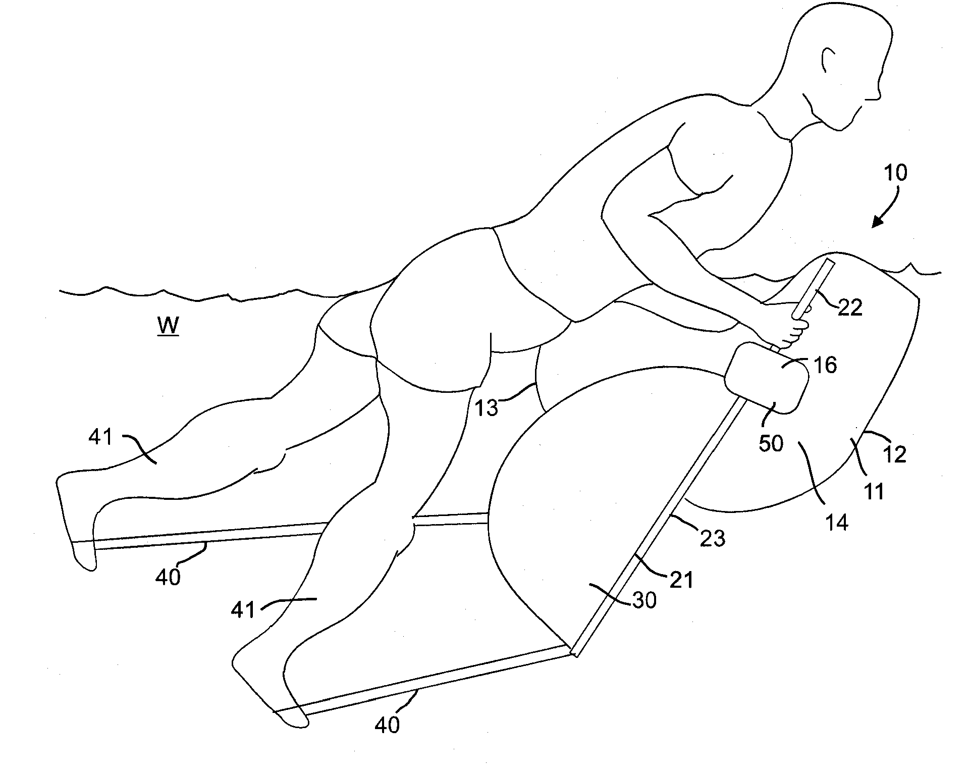
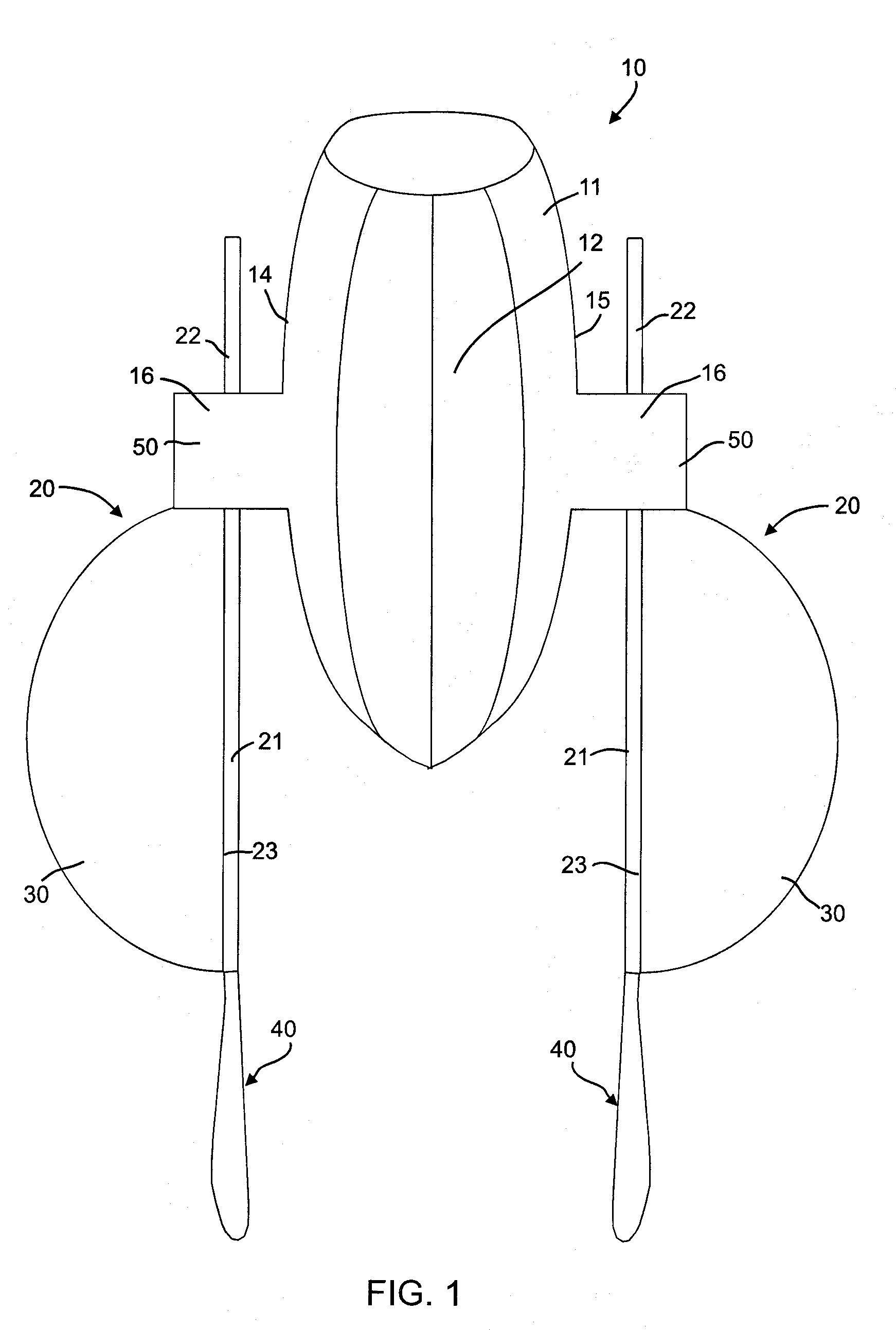
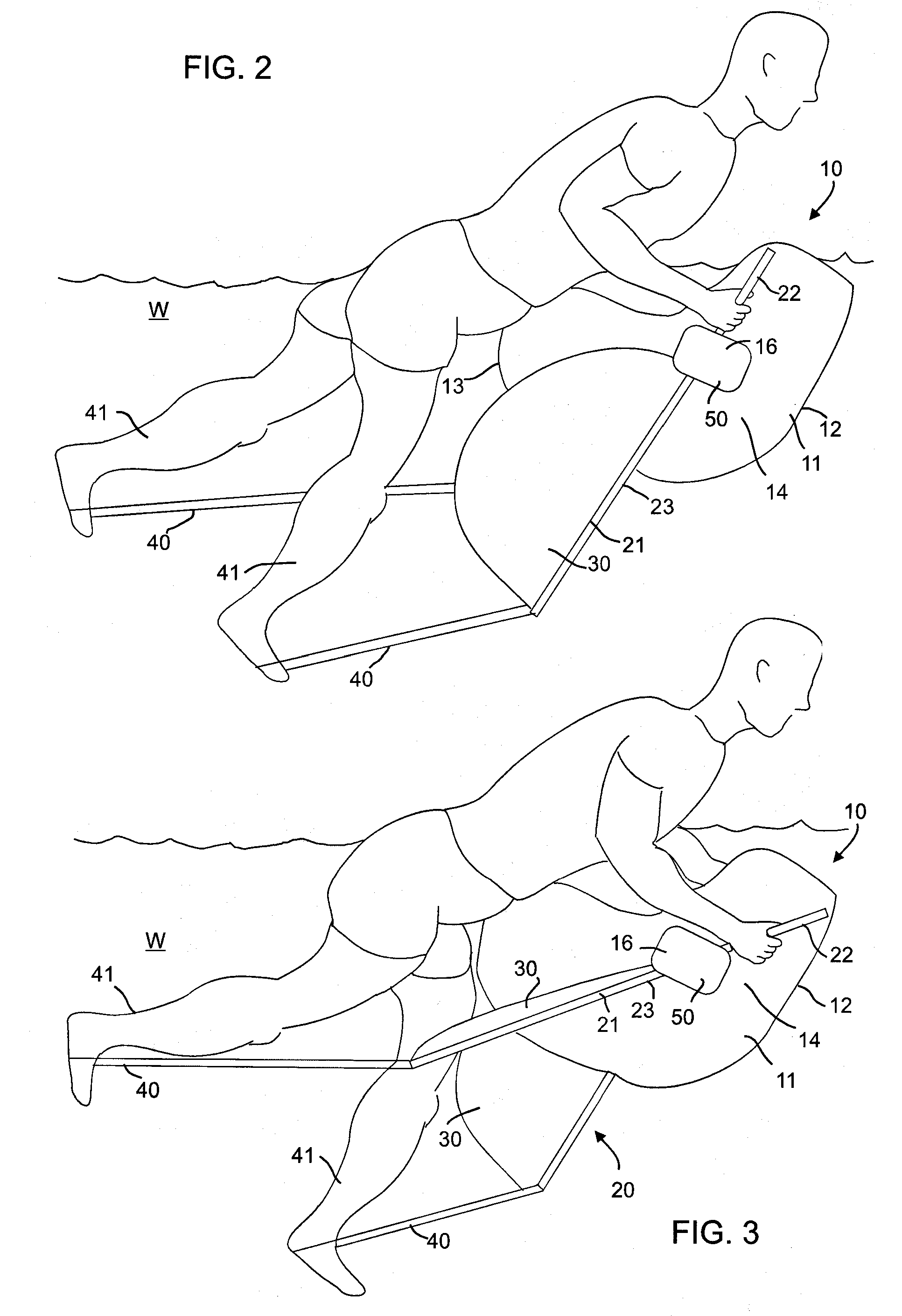
[0016] Referring to the figures, the present application discloses a manually propelled personal floatation apparatus 10. The apparatus comprises a central body portion 11 capable of being buoyant in a body of water W that has a front 12, a back 13 and two transversely opposing sides 14, 15.

[0017] A propulsion structure 20 is pivotally coupled to at least one side 14 of the central body portion 11 with a pivoting structure 16 and depends downwardly therefrom into the water W. In an embodiment, a depending propulsion structure 20 may be pivotally coupled to each respective side 14, 15. In such an embodiment, the respective propulsion structures 20 will be substantially similar in design and configuration but will be inverse relative to each other.

[0018] The back 13 of the central body portion 11 may have an ergonomic shape to support a user's torso and position during use. The back 13 may include a flattened portion adapted to abut the user's torso. The front 12 of the central body...


PUM


Abstract

A personal floatation apparatus comprising a central body portion, adapted to float in a body of water, with a propulsion structure pivotally coupled to the body having an elongated rod member with upper and lower portions and a fin member pivotally coupled intermediate the respective portions. The upper and lower portions are inversely pivotal relative to each other, wherein when the upper portion is disposed forwardly and the lower portion is disposed rearwardly, relative to the body, and vice-versa. The fin member is adapted to extend substantially perpendicular from the body when the lower portion is moved from the forward to rearward positions, thereby encouraging forward movement of the floatation apparatus caused by water resistance acting upon the fin member. The fin member is adapted to lay substantially parallel to the body when the lower portion is moved from the rearward to the forward position, thereby encouraging continued forward movement in a gliding manner.

Description

CROSS REFERENCE TO RELATED APPLICATIONS [0001] This is a continuation of U.S. patent application Ser. No. 10 / 708,627, filed on Mar. 16, 2004, which is a continuation of U.S. patent application Ser. No. 10 / 604,139, filed on Jun. 27, 2003, and titled “Manually Propelled Personal Flotation Device,” now U.S. Pat. No. 6,736,688.BACKGROUND OF INVENTION [0002] The present application relates generally to personal floatation devices and, more particularly, to personal floatation devices that are manually propelled in a body of water. [0003] It is well known that personal floatation devices, such as air-encapsulating inner tubes and the like, can be propelled by a user with simple hand and / or foot movement. It is also well known that such movement can be maximized and enhanced with the utilization of fin-like structures, typically coupled to a user's foot, to maximize water resistance to cause the floatation device to travel in the desired direction. However, a limitation of such a design is...

Claims


Application Information

Patent Timeline
Patent Type & Authority Applications(United States)
IPC IPC(8): A63B31/00A63B31/10B63H16/18
CPCA63B31/10A63B31/00
Inventor GARWOOD, CLINT
Owner HYDRO BLADE
Why Eureka
Try Eureka