

Micro-electromechanical switching backplane
a micro-electromechanical and backplane technology, applied in the field of optical display devices, can solve the problems of disproportionate increase in the likelihood of defective transistors, inability to achieve so-called “passive matrix” display, and limited display size, and achieve the effect of low cost and similar nonlinear switching output characteristics
- Summary
- Abstract
- Description
- Claims
- Application Information
AI Technical Summary
Benefits of technology
Problems solved by technology
Method used
Image

Examples
Embodiment Construction
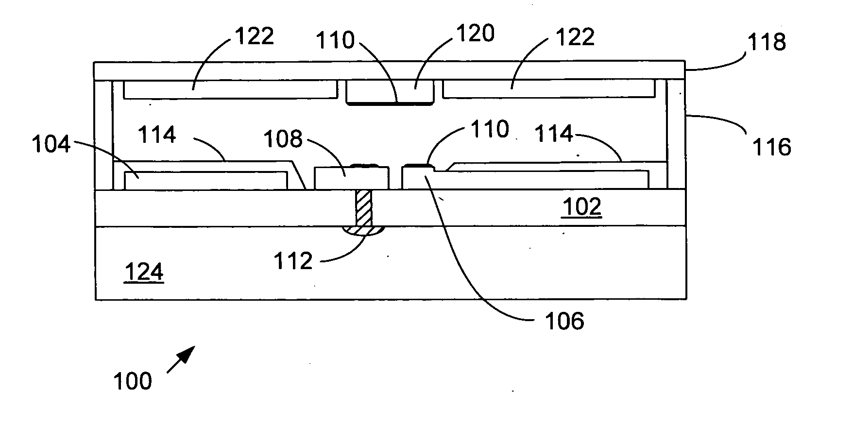
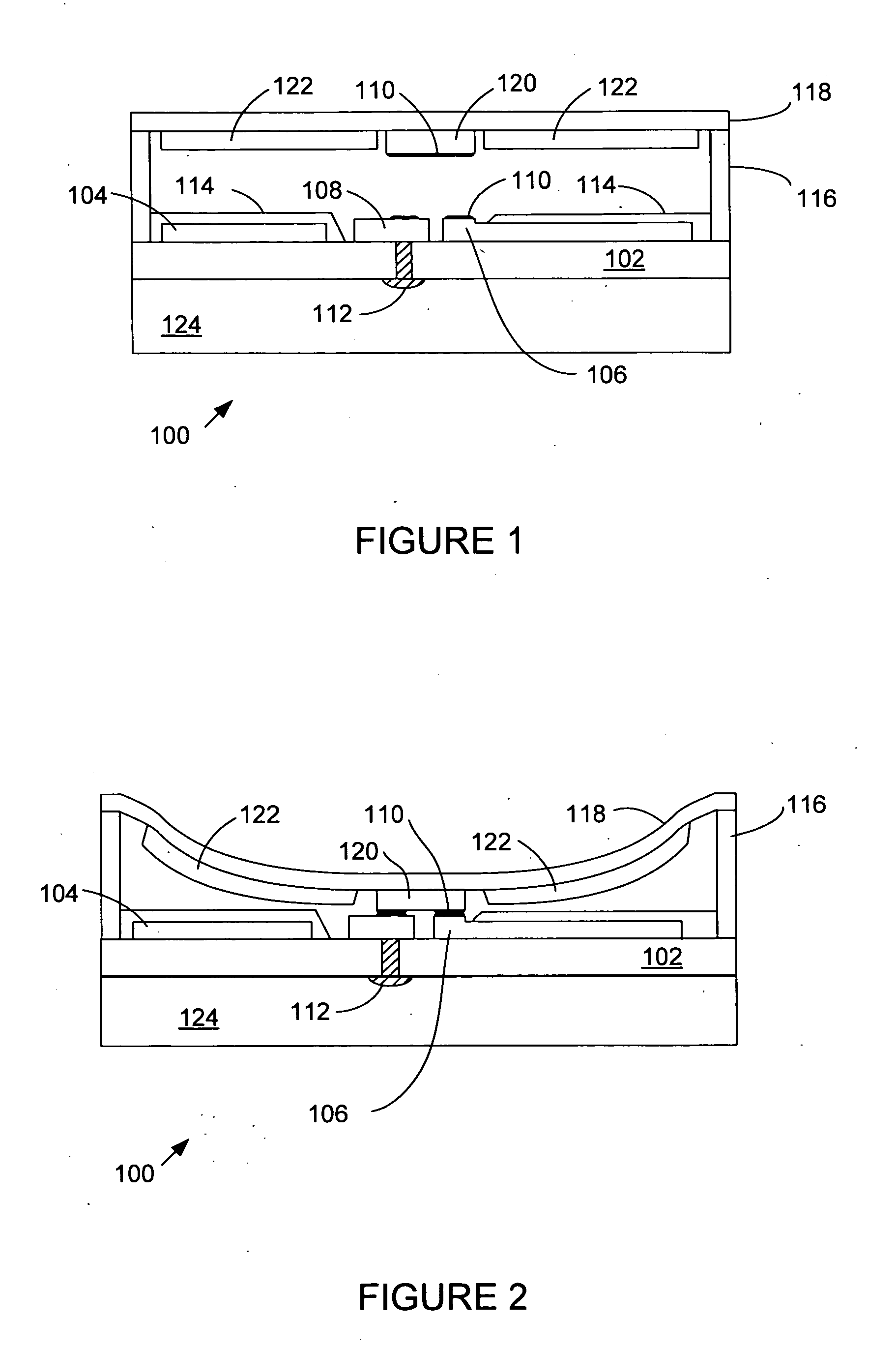
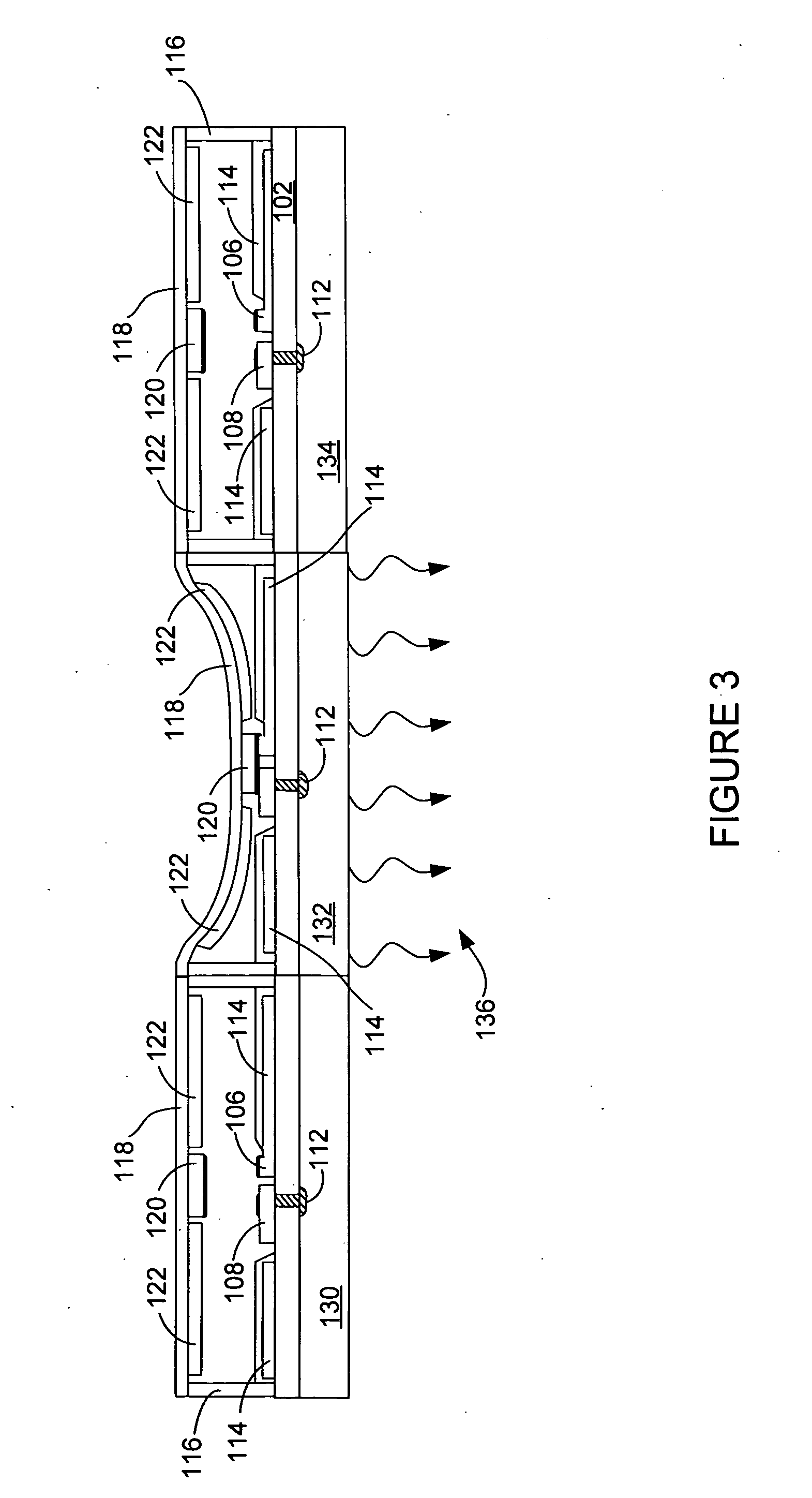
[0010] Embodiments of the present invention provide a matrix of micro electro-mechanical (MEM) switches that can be manufactured using low cost printing techniques on plastic or other membranes. The MEM switches include a substantially non-pliable membrane and a substantially flexible membrane both of which include electrodes that when energized create electrostatic forces that attracts the flexible membrane to the non-pliable membrane. The matrix of MEM switches can be incorporated into the backplane structure of an optical display. Advantageously, the MEM switches can create similar nonlinear switching output characteristics to the semiconductor-based “active matrix” backplane.
[0011] In one embodiment the MEM switches include a “latching” mechanism such that once closed, the switch will remain in a closed state until instructed to release the state, thereby allowing for displays that do not require continuous and power wasting refreshing. The mechanism of the switch activation in...
PUM
 Abstract
Description
Claims
Application Information