Expandable guide sheath and apparatus and methods for making them
What is Al technical title?
Al technical title is built by PatSnap Al team. It summarizes the technical point description of the patent document.
a guide sheath and expandable technology, applied in the field of expandable guide sheaths, can solve the problems of affecting the safety of the patient, and the risk of the instrument advancing over the guidewire. , to achieve the effect of reducing the risk of the expandable guide sheath kinking or buckling
Inactive Publication Date: 2005-07-07
MEDTRONIC INC
View PDF84 Cites 131 Cited by
Summary
Abstract
Description
Claims
Application Information
AI Technical Summary
This helps you quickly interpret patents by identifying the three key elements:
Problems solved by technology
Method used
Benefits of technology
[0020] Once a distal end of the sheath attains a target location, the expandable sheath may be expanded to an enlarged condition such that the outer lumen extends through the body lumen to the target location. One or more instruments, e.g., a cardiac pacing lead, may be advanced through the outer lumen of the expandable sheath into the target location. Because the inner lumen, and consequently, the elongate member, are at least partially floating within the outer lumen, the stiffening member may move relative to the outer lumen as the expandable sheath extends through tortuous anatomy, thereby reducing the risk of the expandable sheath kinking or buckling. After the one or more instruments are delivered into the target location, the apparatus may be removed.
Problems solved by technology
There are many risks involved with advancing instruments over a guidewire.
For example, a catheter or other instrument may skive or otherwise damage a wall of a vessel, particularly as the instrument passes through narrow passages or tortuous anatomy involving sharp bends.
Such instruments also risk dislodging embolic material or even perforating the vessel wall.
However, the instrument(s), e.g., guide sheath, lead, etc., may have a relatively large cross-section and / or may have a relatively blunt distal tip, making it difficult to advance such instruments as deeply as desired into such small vessels.
Method used
Image
Click on the blue label to locate the original text in one second.
Reading with bidirectional positioning of images and text.
Examples
Embodiment Construction
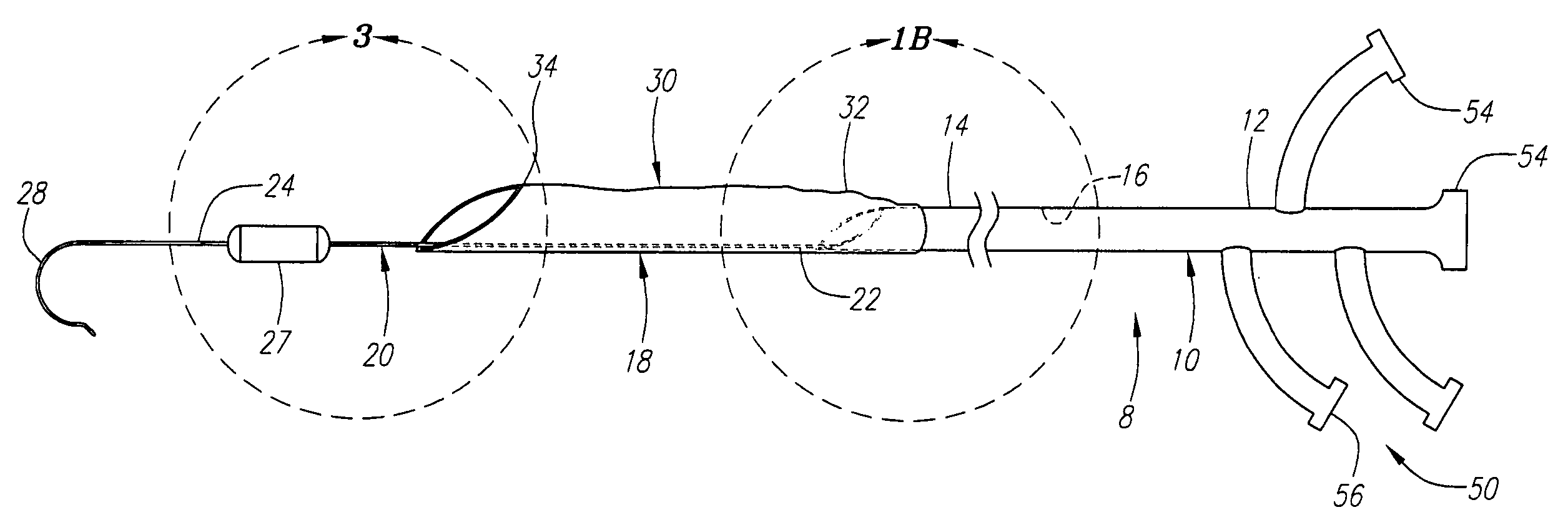
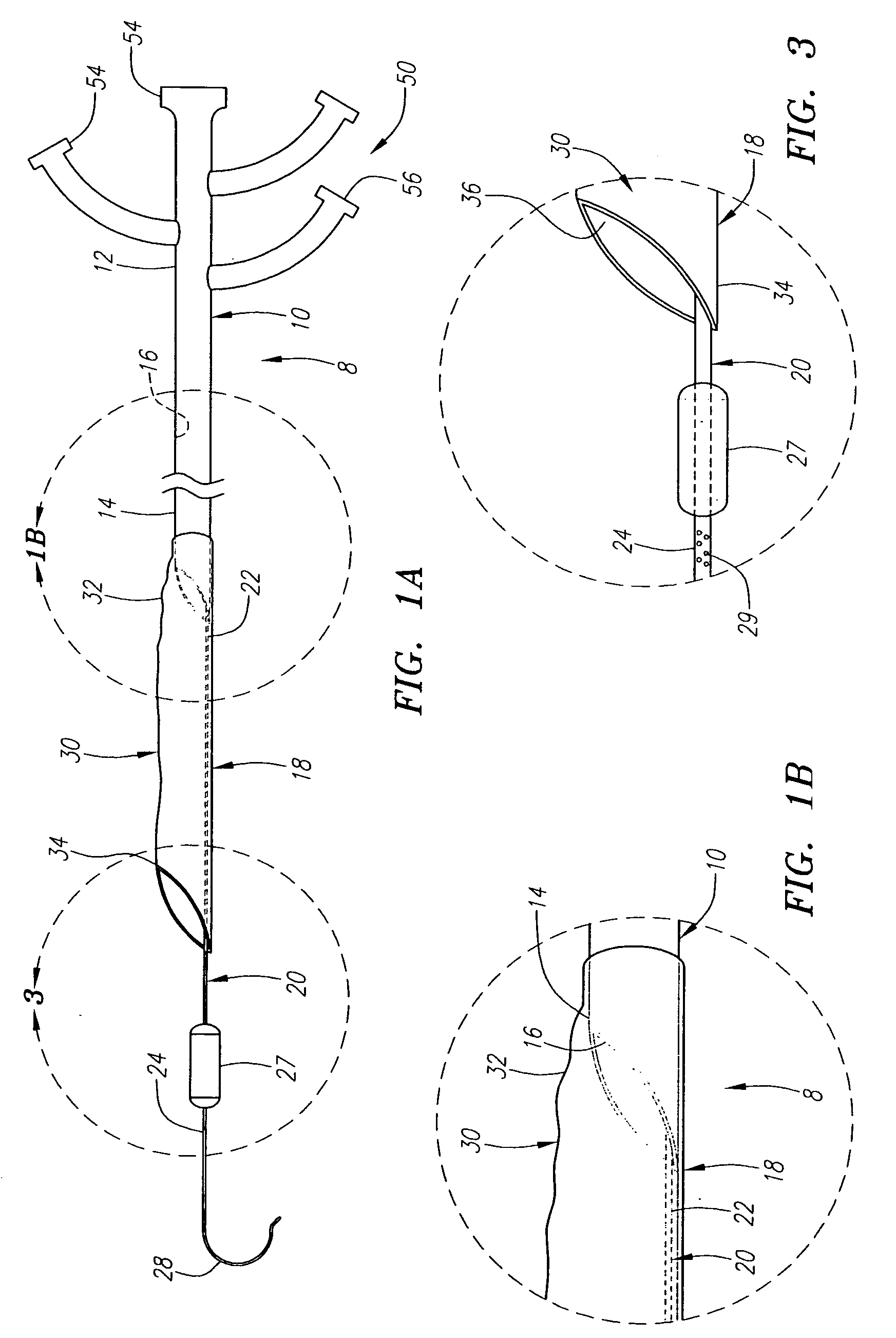
[0059] Turning to the drawings, FIGS. 1A and 1B show a first embodiment of an apparatus 8 for providing access within a body lumen (not shown) and / or for delivering one or more instruments (also not shown) within a body lumen, such as a vessel within a patient's vasculature, a passage within a patient's gastrointestinal tract, urogenital tract, respiratory tract, lymphatic system, and the like.
[0060] Generally, the apparatus 8 includes a tubular proximal portion 10 and an expandable distal portion 18. The tubular proximal portion 10 is an elongate tubular member, e.g., a catheter, sheath, and the like, including a proximal end 12, a distal end 14 sized for insertion into a body lumen, and a lumen 16 extending between the proximal and distal ends 12, 14. Optionally, the tubular proximal portion 10 may include one or more additional lumens (not shown), e.g., for receiving a guide wire, inflation media, and / or for perfusion, as described further below. Such additional lumens may be di...
PUM
Abstract
Apparatus and methods are provided for providing access to a body lumen. The apparatus includes a tubular member including a proximal end, a distal end sized for insertion into a body lumen, and a lumen extending between the proximal and distal ends. A pushable stiffening member extends from the distal end of the tubular member, the elongate member terminating in a distal tip. An expandable sheath extends along at least a portion of the stiffening member, the sheath being expandable from a contracted condition to minimize a profile of the sheath to allow insertion along with the stiffening member into a body lumen, and an enlarged condition wherein the sheath at least partially defines a lumen communicating with the tubular member lumen. In one embodiment, the sheath includes an outer lumen and an inner lumen floating within the outer lumen, and the stiffening member is carried in the inner lumen.
Description
[0001] This application claims benefit of provisional applications Ser. Nos. 60 / 508,489, 60 / 508,490, and 60 / 508,491, all filed Oct. 2, 2003, and 60 / 551,901, filed Mar. 9, 1004. The entire disclosures of these applications are expressly incorporated herein by reference.FIELD OF THE INVENTION [0002] The present invention relates generally to apparatus and methods for delivering instruments and / or agents during a medical procedure, and, more particularly, to guide sheaths for accessing body lumens and / or delivering instruments into body lumens of a patient, and to methods for making and using them. BACKGROUND [0003] Minimally invasive procedures have been implemented in a variety of medical settings, e.g., for vascular interventions, such as angioplasty, stenting, embolic protection, electrical heart stimulation, heart mapping and visualization, and the like. These procedures generally rely on accurately navigating and placing instruments within a patient's vasculature. [0004] During s...
Claims
Application Information
Patent Timeline
Application Date:The date an application was filed.
Publication Date:The date a patent or application was officially published.
First Publication Date:The earliest publication date of a patent with the same application number.
Issue Date:Publication date of the patent grant document.
PCT Entry Date:The Entry date of PCT National Phase.
Estimated Expiry Date:The statutory expiry date of a patent right according to the Patent Law, and it is the longest term of protection that the patent right can achieve without the termination of the patent right due to other reasons(Term extension factor has been taken into account ).
Invalid Date:Actual expiry date is based on effective date or publication date of legal transaction data of invalid patent.
Patent Type & Authority Applications(United States)