
Two-wheel type driving board

a driving board and two-wheel technology, applied in the direction of skateboards, vehicle components, sport apparatus, etc., can solve the problems of unstable condition of the board b>1/b>, user inconvenience,

Inactive Publication Date: 2005-08-11
PARK SANG HO
View PDF4 Cites 9 Cited by
  • Summary
  • Abstract
  • Description
  • Claims
  • Application Information

AI Technical Summary

Benefits of technology

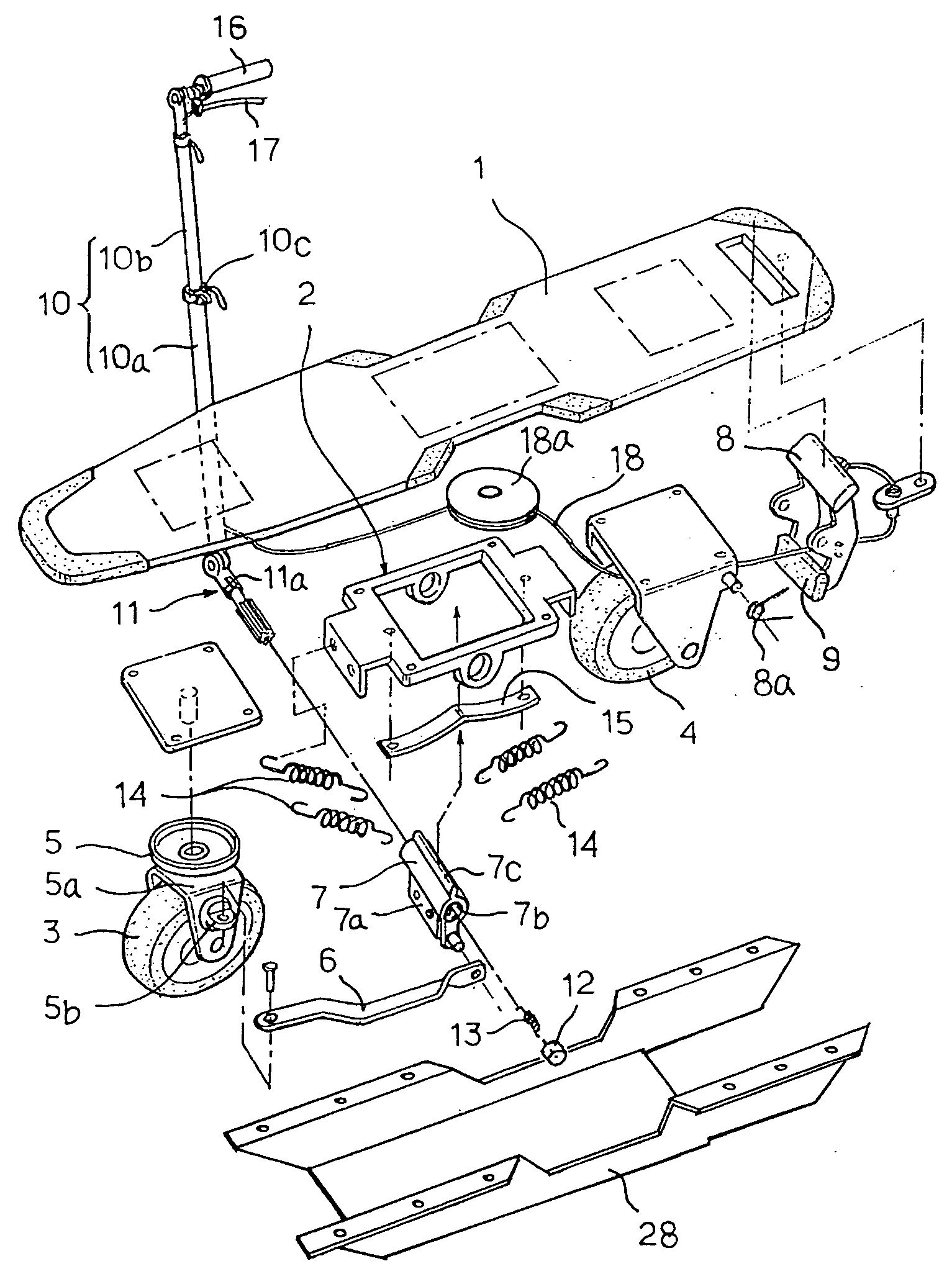
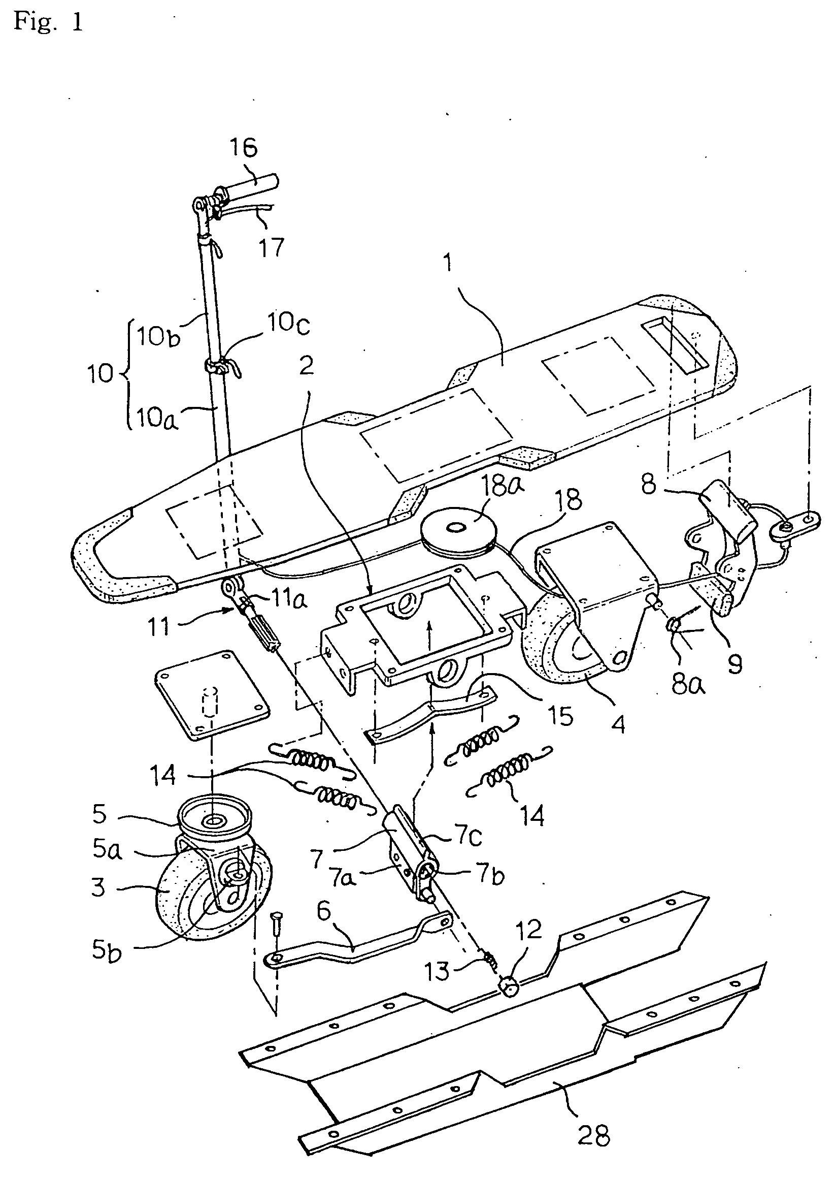
[0007] In order to accomplish the above object the present invention provides a two-wheel type driving board comprises: a board plate; a front wheel and a rear wheel arranged in the straight line under the driving plate through an axis establishing member, said front wheel and rear wheel consisted of one roller, respectively, and said front wheel combined to a rotating member to be rotated 360 degrees so that the front wheel can freely change its driving direction; a connector connected its one side to a wheel establishing member of the rotating member, connected its other side to an axis holder which is axis-established to the axis establishing member so that the front wheel can freely change its driving direction in left or right by driving the connector in forward or backward according to the rotation of the axis holder; a control lever, which is mounted a break lever and a handle, combined to the one side of the axis holder via a central axis so that it can control the rotation of the axis holder; and stepping member, which is attached a rubber plate to be contacted or separated to or from the rear wheel, elastically established to the rear side of the board plate via a spring, said the stepping member connected to the break lever attached to the handle via a strong wire.

Problems solved by technology

Furthermore, because it is difficult to change the driving direction while driving, the user once stop the board 1′ and turn the driving direction thereby causing the user to be inconvenienced.
However, at this time the board 1′ lifts its front side thereby causing the board 1 to be placed in an unstable condition.

Method used


Image

  • Two-wheel type driving board
  • Two-wheel type driving board
  • Two-wheel type driving board

Examples


Embodiment Construction

[0020] Now, the present invention will be in detail described with reference to the drawings.

[0021] A two-wheel type driving board according to the present invention mainly contains a board plate 1 that serves to place a user's feet, a front wheel 3 and a rear wheel 4 which are consisted of one roller respectively. The front wheel 3 and the rear wheel 4 are arranged is straight line via an axis-establishing member 2.

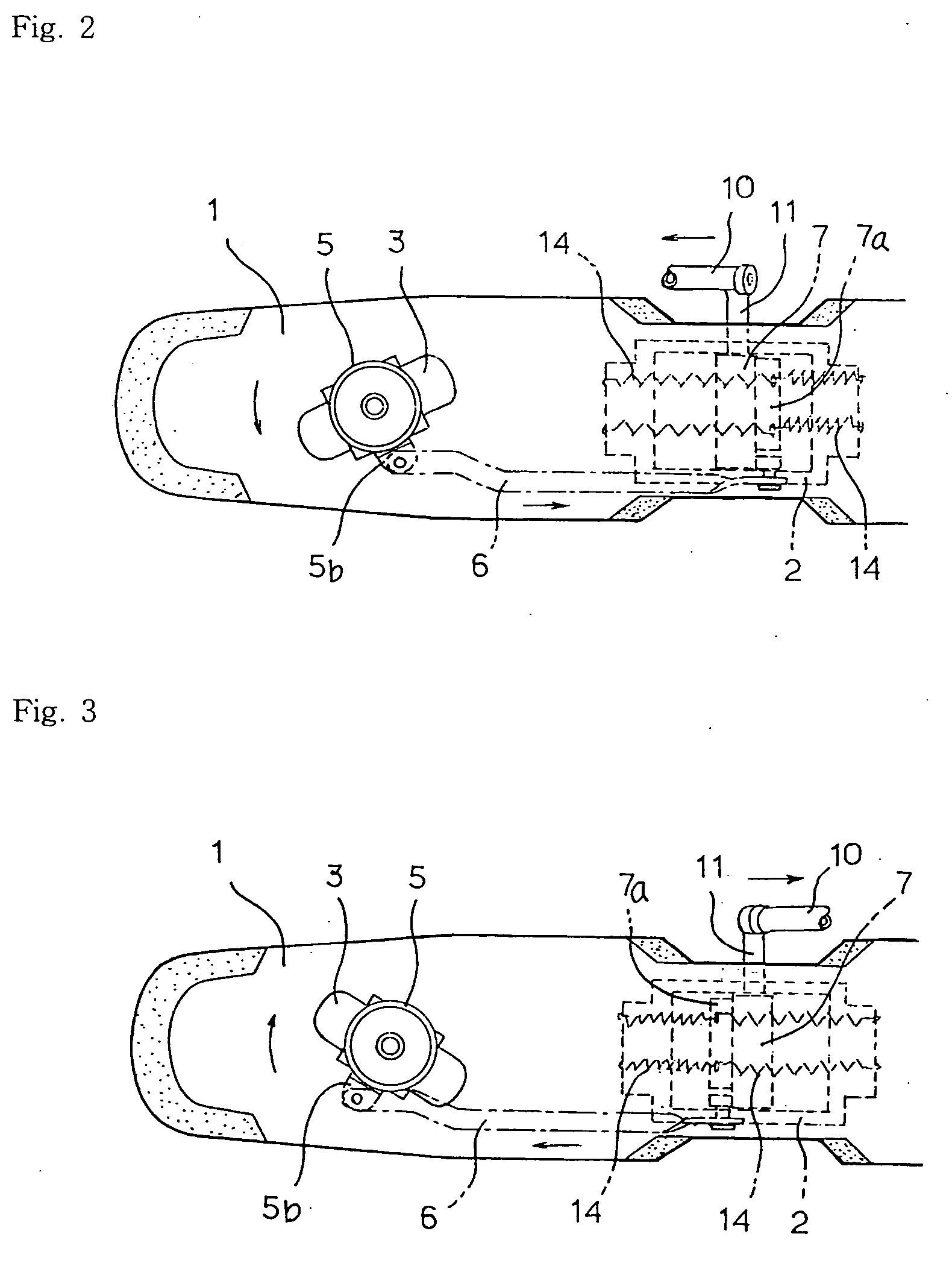
[0022] The front wheel 3 can rotate by 360 degrees because it is combined to a rotation member 5 then it can freely change its driving direction. That is, the front wheel 3 can be its driving direction controlled because a connector 6 is on one end connected to a front wheel driving axis establishing member 5a and is on its other end connected to a rotation axis holder 7 so that the front and rear driving according to the rotation of the axis holder 7 can control the driving direction of the front wheel 3.

[0023] As shown in FIGS. 2 and 3, the front wheel 3 is at its d...


PUM


Abstract

The present invention relates to a two-wheel type driving in which the board is established with two wheels thereunder so that a user can enjoy the speed and the sense of equilibrium at high level because the user can control its driving direction by his body and the control stick. The board has disposed on its bottom portion a first wheel and a second wheel which each comprise one roller, respectively. The first wheel is capable of rotation by 360 degrees so that the driving direction of the board can be easily changed. That is, the connector is its one end connected at one end to the wheel driving axis establishing portion of the rotating plate and at its other end is connected to the axis holder which is established at the axis establishing portion so that the axis holder is rotated to control the connector in the front and backward directions thereby causing the first wheel to be rotated in the left and right direction.

Description

CROSS REFERENCE TO RELATED APPLICATIONS [0001] This application claims the priority of PCT Application No. PCT / KR01 / 02216 filed on 19 Dec. 2001, and Korean Application 2001 / 0032442 filed on 11 Jun. 2001, the contents of which are hereby incorporated by reference.FIELD OF THE INVENTION [0002] The present invention relates to a two-wheel type driving board in which two wheels are arranged in a straight line at the front side and the rear side under the board plate so that an user enjoys a sense of velocity and a sense of balance control because the user can drive the board by using the body and a control lever in left or right direction. BACKGROUND ART [0003] A conventional skateboard is as shown in FIG. 11 a four-wheel type which is mounted four wheels 3′ and 4′ thereto. The conventional board 1′ is at its rear bottom portion attached a stopper 8′ for stopping the board by the fraction to the ground. The user puts one foot on the board 1′ and kicks off the ground by the other foot. U...

Claims


Application Information

Patent Timeline
IPC IPC(8): A63C17/00A63C17/01A63C17/14
CPCA63C17/01A63C17/013A63C2203/52A63C17/14A63C17/016A63C17/00
Inventor PARK, SANG-HO
Owner PARK SANG HO
Learn More