Implant delivery system

a delivery system and implant technology, applied in the field of systems and techniques, can solve the problems of limited axial movement along the shank, and achieve the effect of avoiding the risk of the impression coping loosening from the carrier

Inactive Publication Date: 2005-09-01
BIOMET 3I LLC
View PDF99 Cites 10 Cited by
  • Summary
  • Abstract
  • Description
  • Claims
  • Application Information

AI Technical Summary

Benefits of technology

[0010] If the clinician so desires, he or she can also utilize the combination of the implant and the carrier to take an impression of the patient's mouth during first stage surgery. An impression coping and its associated bolt can be affixed into the socket of the carrier. The impression coping has at its lower end an expandable non-rotational boss that fits within the carrier's socket. When the bolt is threaded into an internally threaded bore within the impression coping, the boss expands outward such that it becomes press fit into the socket of the carrier. This press fit engagement provides enough retention force so that an impression can be made by the clinician without the risk of the impression coping loosening from the carrier.

Problems solved by technology

The guide is free to move rotationally around the shank, but is limited in its axial movement along the shank.

Method used


Image

  • Implant delivery system
  • Implant delivery system
  • Implant delivery system

Examples


Embodiment Construction

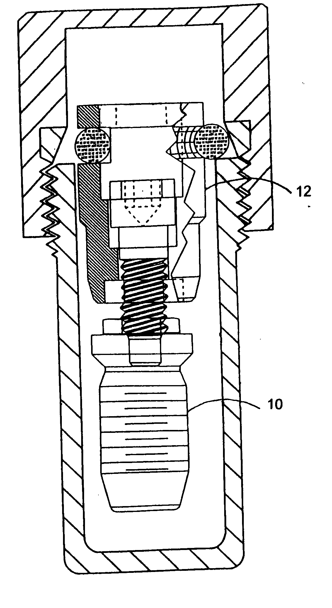
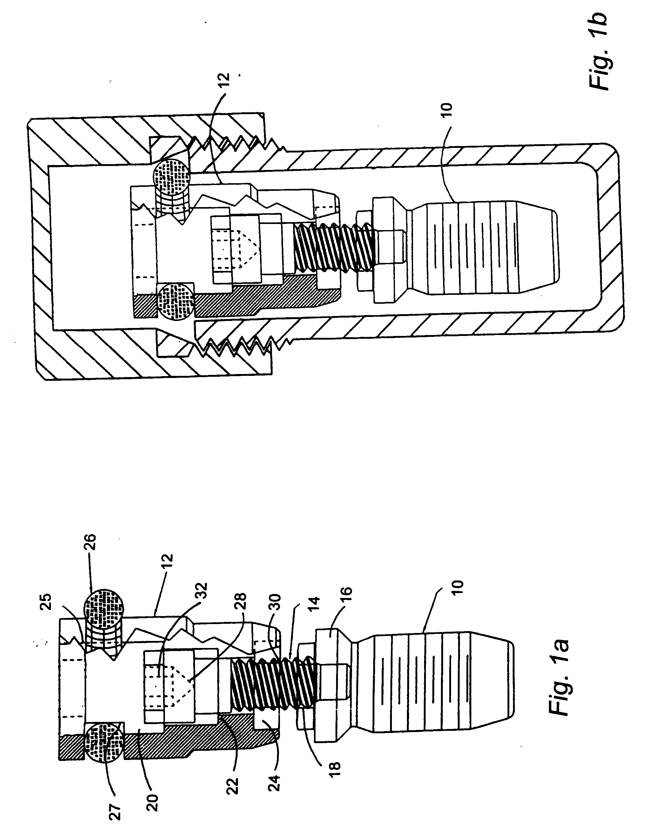
[0035] Referring initially to FIG. 1a, an implant 10 is attached to a carrier 12 with an implant screw 14. The implant 10 includes a non-circular manipulating fitting 16 which, as shown, is in the shape of a hexagon. Extending into the upper region of the implant 10 and through the manipulating fitting 16 is a threaded bore 18.

[0036] The carrier 12 has a through bore 20 extending from its upper end to its lower end. The through bore 20 has various sections. A shoulder 22 is positioned within the through bore20 near the lower end of the carrier 12. Also located at the lower end of the through bore 20 is an implant socket 24 that is configured to mate with the manipulating fitting 16 of the implant 10. At the upper end of the carrier 12 is another socket 25 which, as described below, engages the guide portion of the driver and also may receive a mounting section of an impression coping. The socket 25 includes a non-circular internal surface (usually hexagonal) for non-rotational enga...


PUM


Abstract

An implant delivery system includes a carrier that is attached to an implant. The carrier includes a main body having a lower portion to be attached to the implant and an upper portion. The upper portion includes an internally threaded section having a polygonal internal cross-section. The polygonal cross-section engages a tool that applies torque to install the implant into bone. The threaded section receives a threaded portion of a secondary component to be coupled to the carrier after the implant has been installed. One secondary component is a gingival healing component. Thus, the combination of the carrier and the gingival healing component acts as a healing abutment after the carrier has been used to install the implant.

Description

RELATED APPLICATIONS [0001] This application is a continuation-in-part of application Ser. No. 09 / 416,221, filed Oct. 12, 1999, entitled “Implant Delivery System”; which is a continuation of application Ser. No. 09 / 057,087, filed Apr. 8, 1998, and issued as U.S. Pat. No. 5,964,591 on Oct. 12, 1999, entitled “Implant Delivery System”; which claimed the benefit of priority of Application No. 60 / 043,181, filed Apr. 9, 1997, entitled “Implant Delivery System.”FIELD OF THE INVENTION [0002] The invention relates to a system and a technique for delivering and installing an implant in living bone. Specifically, the system includes an implant and a carrier attached thereto that are packaged together and delivered to the installation site within the living bone. The system also includes a variety of tools that provide flexibility in the installation process and additional components that permit the taking of impressions during first stage surgery. BACKGROUND OF THE INVENTION [0003] It is know...

Claims


Application Information

Patent Timeline
Patent Type & Authority Applications(United States)
IPC IPC(8): A61C8/00
CPCA61C8/0001A61C8/0089A61C8/0087A61C8/008
Inventor BEATY, KEITH D.LAZZARA, RICHARD J.ROGERS, DAN P.GOODMAN, RALPH E.
Owner BIOMET 3I LLC
Why Eureka
Try Eureka