Armature, wire dot printer head and wire dot printer

a printer head and wire dot technology, applied in the field of wire dot printers, can solve the problems of insufficient joining force, unable to obtain sufficient joining force, and difficulty in reducing a dimensional tolerance at the engagement section, and achieve the effect of durable armatures

Inactive Publication Date: 2005-09-15
TOSHIBA TEC KK
View PDF38 Cites 22 Cited by
  • Summary
  • Abstract
  • Description
  • Claims
  • Application Information

AI Technical Summary

Benefits of technology

[0010] An object of the present invention is to give...

Problems solved by technology

On the other hand, it has been known that an eddy current loss is caused by a ripple (change) in a flux passing through the magnetic circuit forming member.
When a spot welding is used for welding plural plate-like members, sufficient joining force cannot be obtained since sufficient pressure cannot be applied to these members.
Therefore, plural plate-like members are not at all joined, or even if they are joined once, they do not withstand the pivotal movement of the armature during the printing operation, resultin...

Method used


Image

  • Armature, wire dot printer head and wire dot printer
  • Armature, wire dot printer head and wire dot printer
  • Armature, wire dot printer head and wire dot printer

Examples


Embodiment Construction

[0023] Preferred embodiments for carrying out the present invention will be explained with reference to FIGS. 1 to 6.

[0024] [Wire Dot Printer Head]

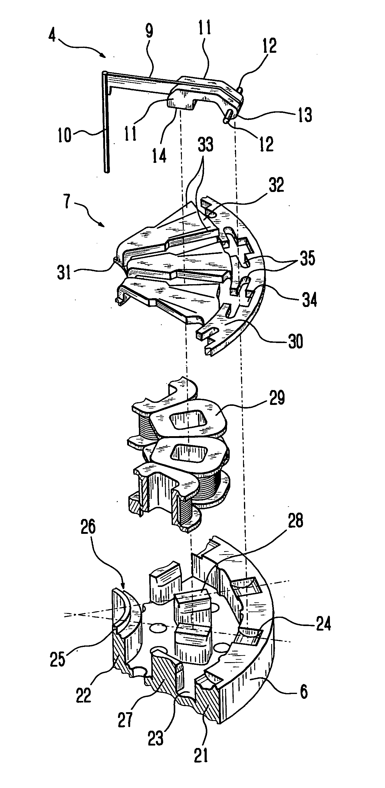
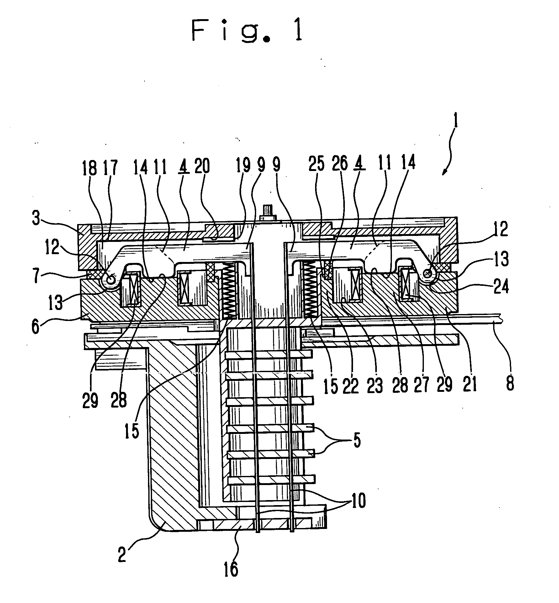
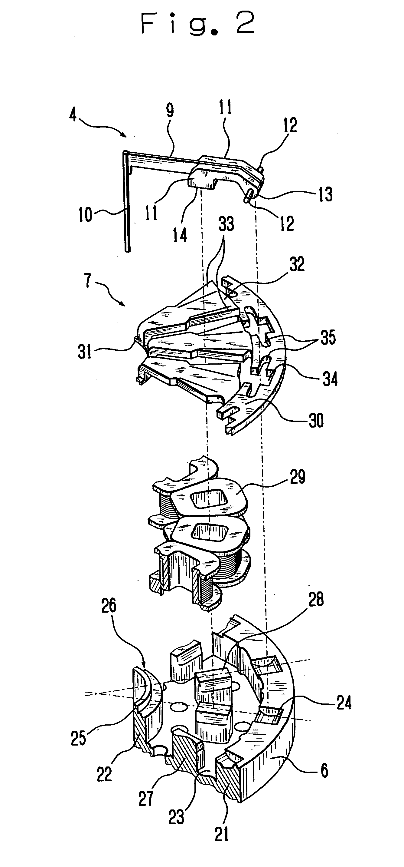
[0025] Firstly, the entire construction of a wire dot printer head 1 will be explained with reference to FIGS. 1 to 4. FIG. 1 is a front view in central vertical section schematically showing a wire dot printer head 1 according to the embodiment and FIG. 2 is an exploded perspective view schematically showing a part of the wire dot printer head 1.

[0026] The wire dot printer head 1 has a front case 2 and a rear case 3 coupled together with a mounting screw (not shown). Disposed between the front case 2 and the rear case 3 are armatures 4, wire guides 5, yoke 6, armature spacer 7, and circuit board 8.

[0027] Each of the armatures 4 has an arm 9 that is formed into a plate-like shape and supports a printing wire (hereinafter simply referred to as a wire) 10 at one end thereof in the lengthwise direction (in the direction in which the arm 9...


PUM


Abstract

In order to obtain joining force endurable for high-speed printing and realize an enhancement in magnetic characteristic, a plate-like arm for supporting a printing wire is laminated with a magnetic circuit forming member that is composed by laminating plural plates for forming a magnetic circuit, wherein a weld zone is formed on the laminated surface of the arm and plates with laser beam irradiation for fixing the arm and the magnetic circuit forming member with the weld zone.

Description

CROSS REFERENCE TO RELATED APPLICATION [0001] The present application is based on Japanese Priority Document P2004-70484 filed on Mar. 12, 2004, the content of which is incorporated herein by reference. BACKGROUND OF THE INVENTION [0002] 1. Field of the Invention [0003] The present invention relates to a wire dot printer, a wire dot printer head used for this and an armature used for this, and more particularly to an armature formed by laminating plural flat plates, a wire dot printer head using this and a wire dot printer. [0004] 2. Discussion of the Background [0005] There has been known a wire dot printer head wherein an armature with a printing wire coupled thereto is pivoted between a printing position and a stand-by position, and when the armature is pivoted to the printing position, a tip of the wire is brought into collision with a printing medium to effect printing. In a certain wire dot printer head of this type, there has been proposed a device wherein a magnetic flux is ...

Claims


Application Information

Patent Timeline
IPC IPC(8): B41J2/275B41J2/27
CPCB41J2/27
Inventor TSUCHIYA, KEISHITERAO, YASUNOBUKAWAGUCHI, TAKAHIRO
Owner TOSHIBA TEC KK
Why Eureka
Try Eureka