

Apparatus and method for providing high intensity non-coherent light and for speckle reduction
a technology of non-coherent light and optical system, applied in the direction of fixed installation, lighting and heating apparatus, instruments, etc., can solve the problem of particularly problematic specks
- Summary
- Abstract
- Description
- Claims
- Application Information
AI Technical Summary
Benefits of technology
Problems solved by technology
Method used
Image

Examples
Embodiment Construction
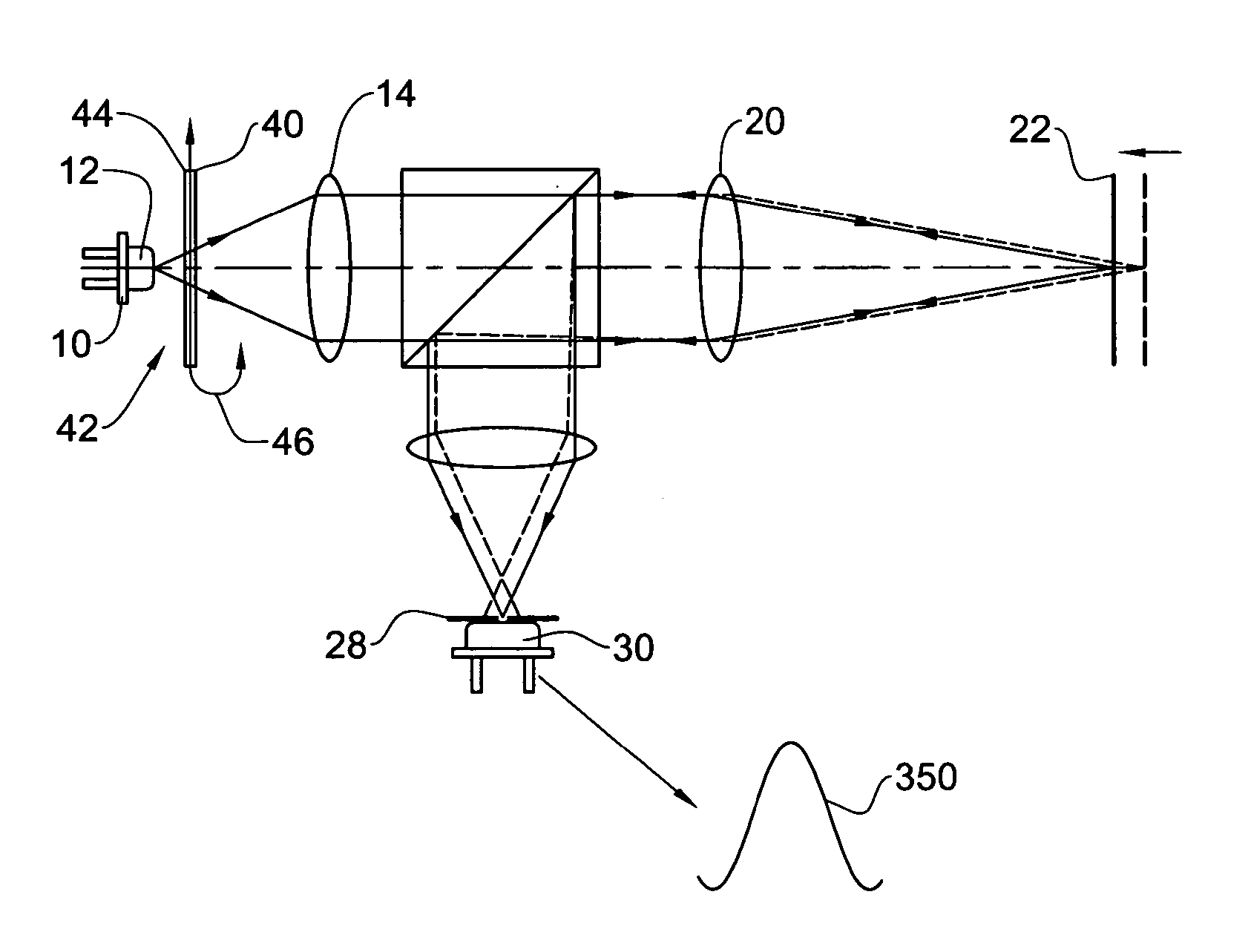
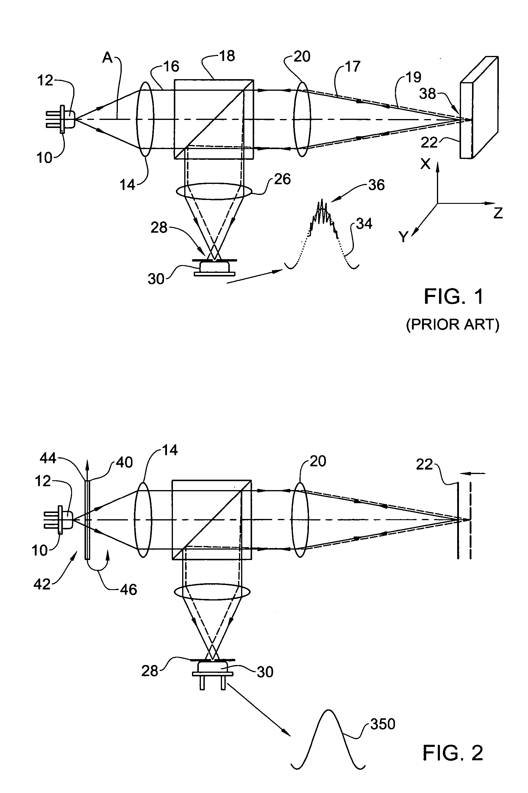
[0051]FIG. 1 shows a typical prior art apparatus for determining a 3-D profile, or topography, of the surface of an object / specimen, e.g. a tooth, at a desired lateral and axial resolution. The apparatus is a confocal imaging system comprising a laser 10, which constitutes a source of coherent light 12; a collimating lens 14 disposed in front of the laser for collimating the emitted light into a beam 16; a beam splitter 18 through which the collimated beam 16 passes; an optical imaging component in the form of an objective lens 20 for focusing the light beam into a beam 17 (hereinafter ‘incident light beam’), on a non-flat specimen 22 whose topography is to be determined. The above components are disposed along an optical axis A. The specimen 22 is shown in a perspective view to emphasize that it contains a depth (in Z-direction coinciding with the optical axis A) as well as a length and a width (in an X-Y plane perpendicular to the optical axis A). The incident light beam 17 that i...
PUM
 Abstract
Description
Claims
Application Information