Hair styling iron having a pick and comb

Inactive Publication Date: 2005-10-27
PARK HUI SUK
View PDF19 Cites 55 Cited by
  • Summary
  • Abstract
  • Description
  • Claims
  • Application Information

AI Technical Summary

Problems solved by technology

This constant changing and swapping tools takes time and increases the possibility that the hair styl

Method used


Image

  • Hair styling iron having a pick and comb
  • Hair styling iron having a pick and comb
  • Hair styling iron having a pick and comb

Examples


Embodiment Construction

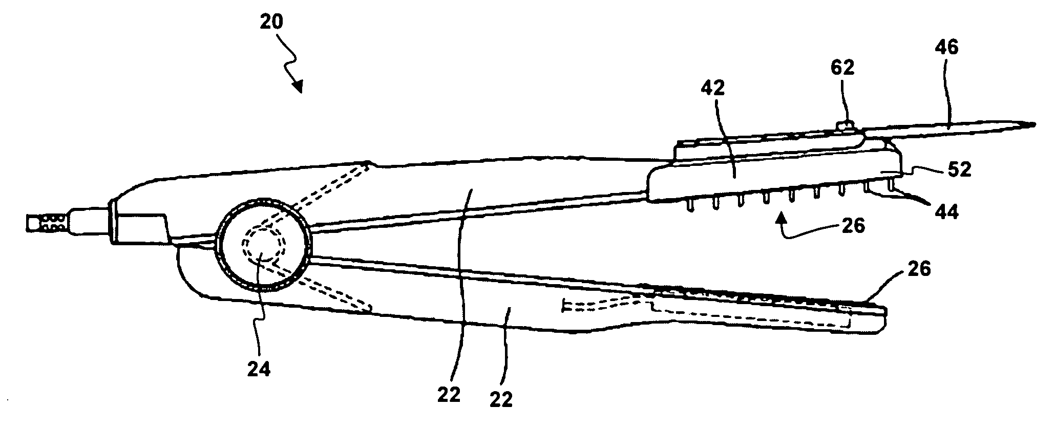
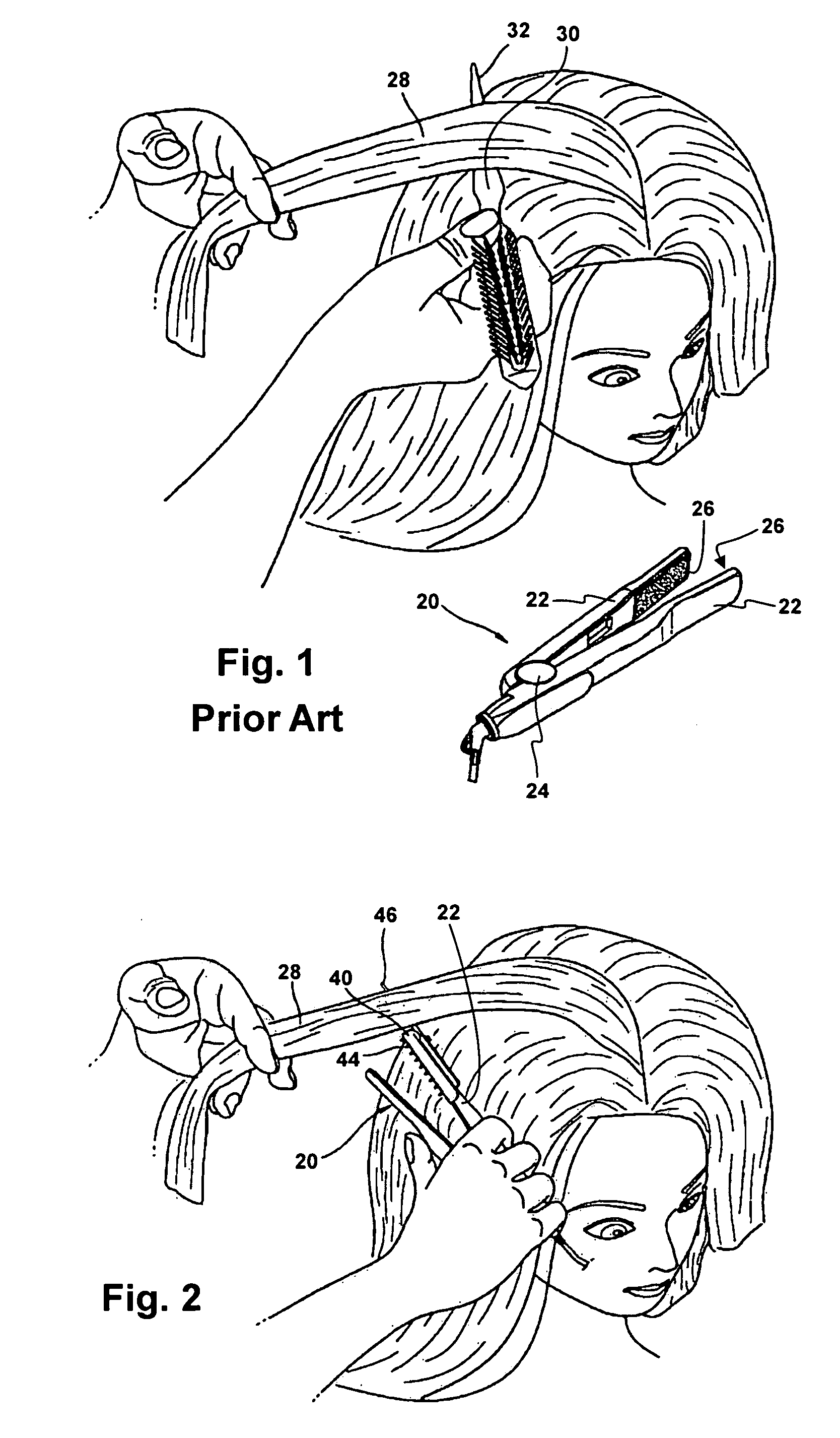
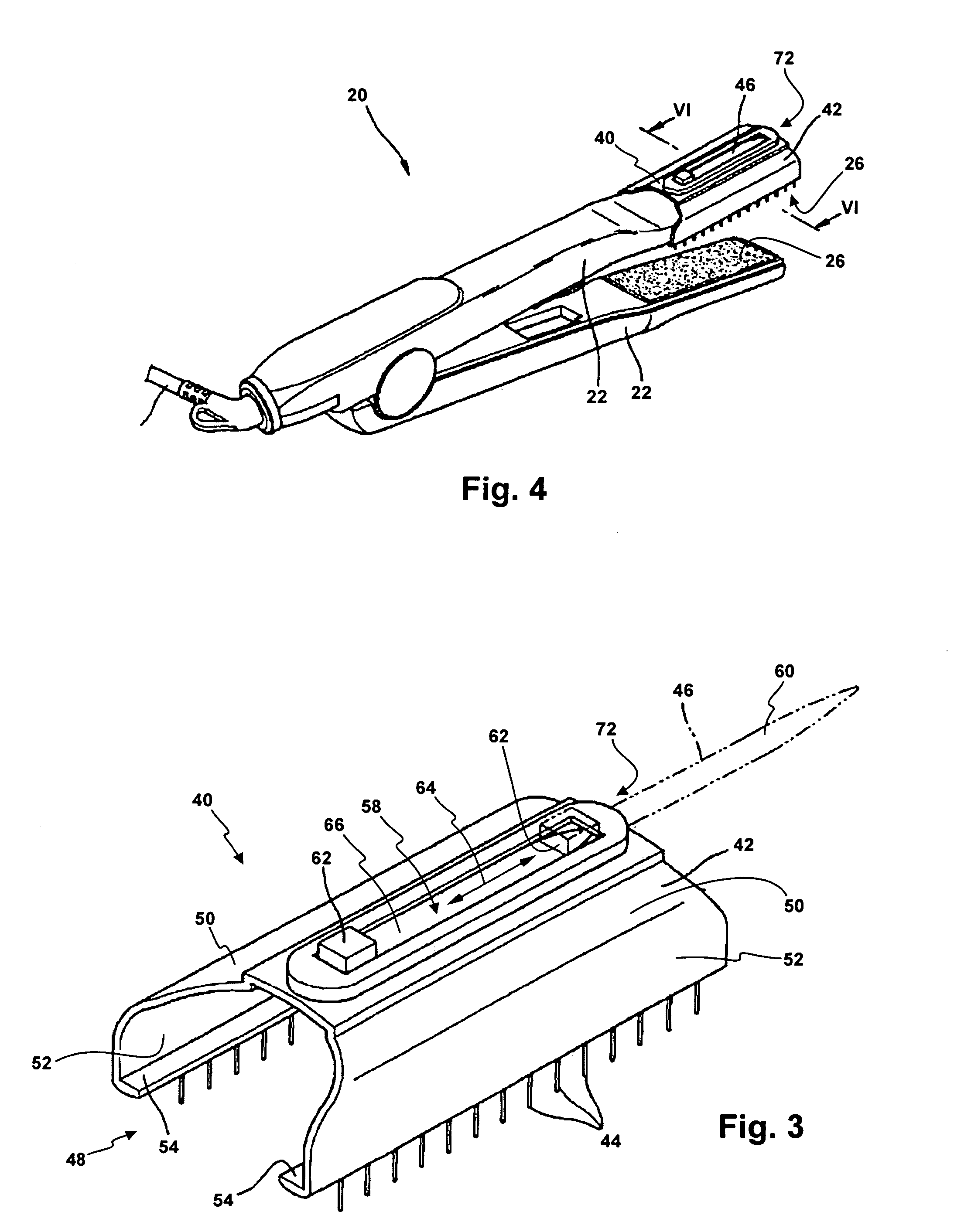
[0018] With reference now to the drawings, and in particular with reference to FIG. 2, there is depicted a person having their hair straightened with the use of hair styling iron 20 and pick and comb attachment 40 attached to a heating element arm 22. Heating element arms 22 each have a hinge end near hinge 24, and a heating element end near heating elements 26. In a preferred embodiment, heating elements 26 have flat surfaces that cooperate with each other to straighten hair.

[0019] As shown more clearly in FIG. 3, pick and comb attachment 40 includes shell 42, which is shaped and adapted to be removably mounted to the heating element end of heating element arm 22 of hair styling iron 20 (See FIG. 4). A plurality of comb teeth 44 extend or protrude from shell 42 so that they engage hair strands that are contacting the heating element surface 26.

[0020] Pick 46 extends from shell 42 so that it can be used as a parting tool for selecting and separating a bundle of hair 28 (See FIG. 2...


PUM


Abstract

An attachment for a hair styling iron, or a new hair styling iron, includes a hair pick and plurality of comb teeth. The hair pick, which is used for selecting and separating hair, may be moveable between an extended position and a retracted position. The comb teeth are located adjacent to a heating element for extending into the hair when the hair styling iron contacts and moves along the length of a bundle of hair. The attachment may be slid over a heating element arm, wherein a retaining lip hooks around to engage an inner surface of the heating element arm adjacent to the heating element. In another embodiment, a new hair styling iron includes comb teeth adjacent to a heating element of the hair styling iron, and a hair pick that extends beyond the end of a heating element arm of the hair styling iron.

Description

BACKGROUND OF THE INVENTION [0001] 1. Field of the Invention [0002] The present invention relates generally to hair styling devices, and more particularly to an attachment for a hair styling iron having a pick and comb. [0003] 2. Description of the Prior Art [0004] Fashionable hairstyles frequently require the straightening of a person's hair to remove a curl from the hair. Since heat may aid in the straightening of hair, stylists or individuals styling their own hair frequently use a hair styling iron to remove hair curls. Such a hair styling iron is preferably a flatiron, such as styling iron 20 shown in FIG. 1. As illustrated, styling iron 20 includes two heating element arms 22 pivotally connected by hinge 24. One or more heating elements 26 is mounted at the end and on the inside face of each heating element arm 22. When heating element arms 22 are moved toward a closed position, the inside faces of heating element arms 22 come together to heat and flatten a selected bundle of ...

Claims


Application Information

Patent Timeline
IPC IPC(8): A45D1/00A45D1/18A45D2/00A45D2/40A45D19/18
CPCA45D2/002A45D1/18A45D1/04A45D1/08A45D2001/002
Inventor PARK, HUI SUK
Owner PARK HUI SUK
Why Eureka
Try Eureka