Working machine driving unit

a driving unit and working machine technology, applied in the direction of servomotors, instruments, analogue processes for specific applications, etc., can solve the problems of large-scale production costs, small and more unstable torques, and disadvantages of conventional systems, so as to reduce production costs, effectively share excess energy generated, and make up shortfalls in hydraulic fluid

Inactive Publication Date: 2005-11-03
SHIN CATERPILLAR MITSUBISHI LTD CORP
View PDF10 Cites 104 Cited by
  • Summary
  • Abstract
  • Description
  • Claims
  • Application Information

AI Technical Summary

Benefits of technology

[0012] A work machine driving device according to the invention is for operating a working unit by a plurality of hydraulic actuator systems and comprises an engine, a power generating device driven by the engine, a power storage device for storing the electric power generated by the power generating device, a plurality of driving circuits, and one or more supporting circuits. Each driving circuit is provided for each respective hydraulic actuator system and adapted to be operated by electric power supplied from either one of or both the power generating device and the power storage device so as to generate hydraulic pressure, thereby driving each respective hydraulic actuator system. Each supporting circuit serves to feed supporting hydraulic fluid from one driving circuit to another driving circuit to make up shortfall in the hydraulic fluid. As the supporting circuits enable the plurality of driving circuits to effectively share excess energy generated from hydraulic fluid so that the capacity of each driving circuit, which is adapted to generate hydraulic pressure by being operated by electricity supplied from the power generating device or the power storage device, both of which are driven by the engine, can be consequently reduced. Therefore, the inclusion of the supporting circuits enables the various components of the driving circuits to be made compact at reduced production costs.

Problems solved by technology

However, heavy load operation occupies only a part of the entire work period.
When a conventional construction machine equipped with such a high-power engine performs light load operation or medium load operation, which occupies a major part of the entire work, the pressurized oil discharged from the hydraulic pumps 8,9 is throttled by the valve unit 11 and then distributed to the actuators, such as the boom cylinders 3a, the stick cylinder 4a, and the bucket cylinder 5a. Such a conventional system is disadvantageous in such aspects as fuel consumption, noises and production costs.
The conventional driving device presents a problem also in light load operation, which is typically performed under throttled engine power or low engine speed; the lower the engine speed, the smaller and more unstable the torque due to the characteristics of the engine 7.
As a result, the engine 7 becomes prone to stalling or uneven rotation, resulting in unacceptable operatability.
However, as the circuits for driving the respective actuators are provided independently of one another, excess energy is not effectively used by the driving circuits of the respective hydraulic actuators.

Method used


Image

  • Working machine driving unit
  • Working machine driving unit
  • Working machine driving unit

Examples


Embodiment Construction

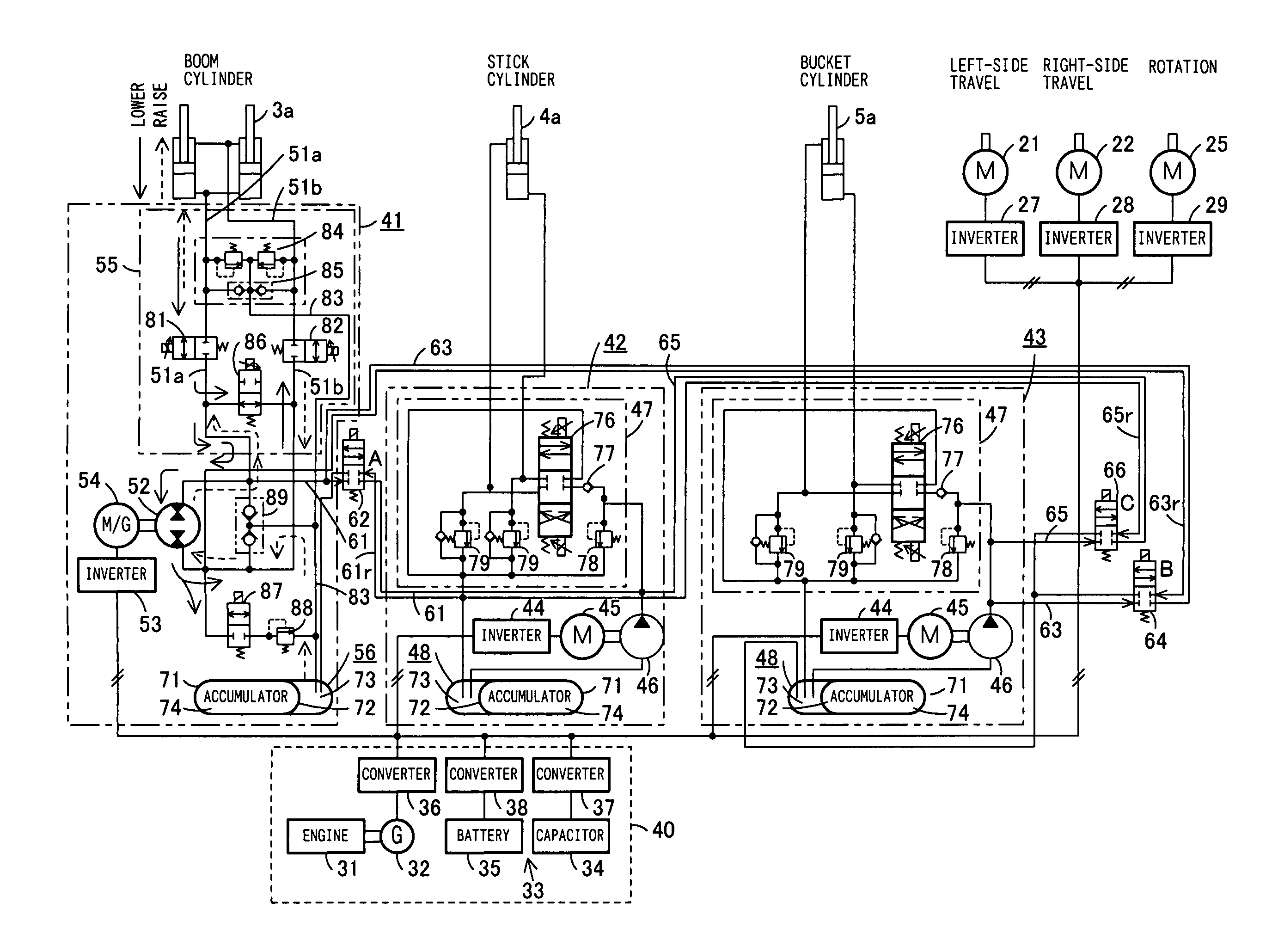
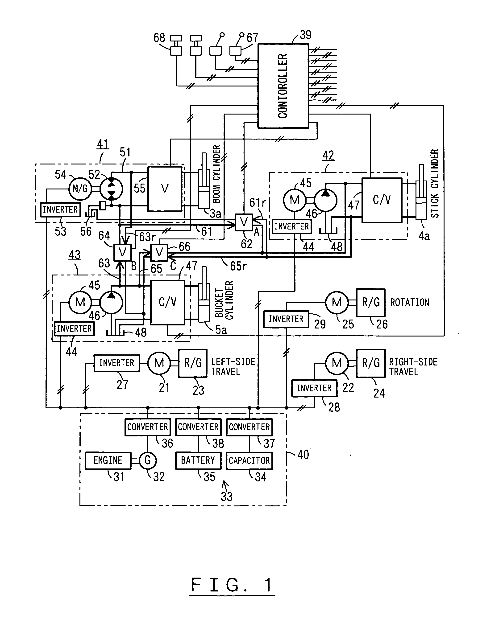
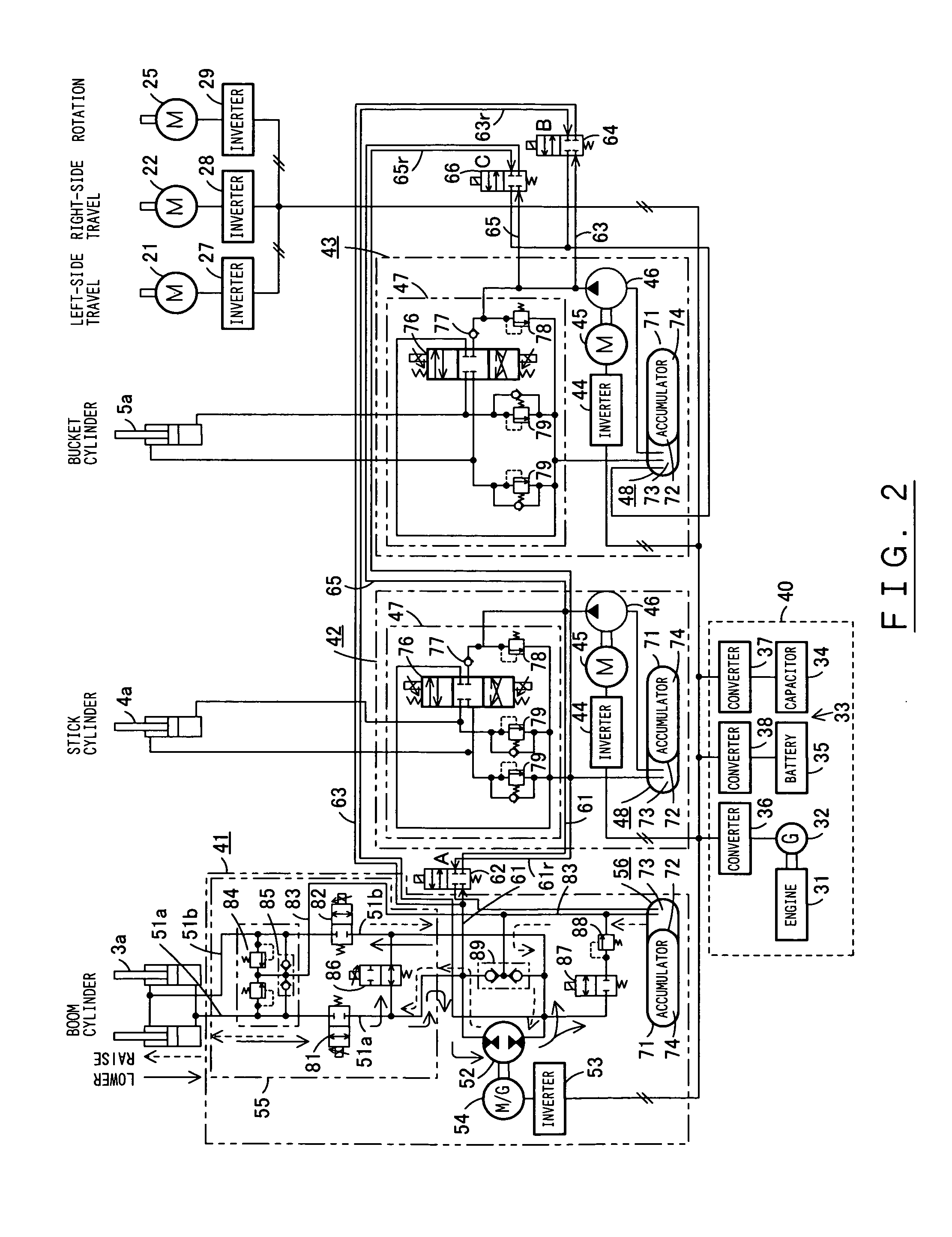
[0031] The present invention is explained in detail, referring to an embodiment shown in FIGS. 1 through 3, another embodiment shown in FIG. 4, and a further embodiment shown in FIG. 5, other embodiments are shown in FIGS. 6 and 7, and another embodiment is shown in FIG. 8. The explanation of the hydraulic excavator shown in FIG. 9 is also used in the explanation of the present embodiments.

[0032]FIG. 1 shows an embodiment of a driving device of a work machine, which is a construction machine, or more precisely, a hydraulic excavator. As shown in FIG. 9, the hydraulic excavator has a working unit 6 comprising a boom 3, a stick 4, and a bucket 5 that are connected sequentially. Shown in FIG. 1 is a circuit diagram of a composite hybrid driving device of the hydraulic excavator. The driving device includes a boom-stick-bucket composite circuit. FIG. 2 shows a circuit diagram that illustrates the circuit diagram of FIG. 1 in more concrete terms.

[0033] As shown in FIG. 1, the working u...


PUM


Abstract

A driving device of a work machine includes a power generator adapted to be driven by an engine, and a power storage device for storing the electric power generated by the power generator. Electric motors and a motor generator, both adapted to be operated by electric power supplied from either one or both of the power generator and the power storage device respectively drive pumps and a pump motor. Supporting circuits for feeding supporting hydraulic oil are provided between a plurality of driving circuits that drive a plurality of hydraulic actuators of a working unit by oil hydraulics generated by the pumps and the pump motor. By enabling the plurality of driving circuits to effectively share excess energy, the invention makes possible a compact construction of a driving device of a work machine.

Description

TECHNICAL FIELD [0001] The present invention relates to a driving device for a hydraulic excavator or any other work machine equipped with a power source that uses both an engine and a power generating device. BACKGROUND OF THE INVENTION [0002]FIGS. 9 and 10 refer to a conventional art. FIG. 9 illustrates the structure of a hydraulic excavator, and FIG. 10 is a circuit diagram showing the structure of its hydraulic system. [0003] Referring to FIG. 9, an upper structure 2 is rotatably mounted on an undercarriage 1. A working unit 6 comprising a boom 3, a stick 4, and a bucket 5 is mounted on the upper structure 2. The boom 3 is attached to the upper structure 2 so that the boom 3 can be swung by means of boom cylinders 3a. The stick 4 is attached to the distal end of the boom 3 so that the stick 4 can be swung by means of a stick cylinder 4a. The bucket 5 is attached to the distal end of the stick 4 and is adapted to be driven by a bucket cylinder 5a. [0004] As shown in FIG. 10, a co...

Claims


Application Information

Patent Timeline
Patent Type & Authority Applications(United States)
IPC IPC(8): E02F9/00E02F9/20E02F9/22F15B11/16F15B11/17F15B15/18F15B21/14H02P5/00
CPCE02F9/2025E02F9/2075E02F9/2217E02F9/2242F15B11/17F15B21/14F15B2211/7142F15B2211/20538F15B2211/20561F15B2211/20576F15B2211/2658F15B2211/315F15B2211/7135F15B2211/20515F15B2211/20569
Inventor MIKI, MASATOSHIMATOBA, NOBUAKI
Owner SHIN CATERPILLAR MITSUBISHI LTD CORP
Why Eureka
Try Eureka