Mechanism for trip-free of the bimetallic plate of a safety switch device

Inactive Publication Date: 2005-12-01
YU TSUNG MOU
View PDF83 Cites 9 Cited by
  • Summary
  • Abstract
  • Description
  • Claims
  • Application Information

AI Technical Summary

Problems solved by technology

A conventional circuit breaker incorporates a fuse between a switch and the circuit such that when there is an electrical overload, the fuse will first melt before the overload causes damages.
However, if the fuse is not properly installed or an improper fuse is used the overload current cannot melt the fuse and a disaster can be resulted.
Nevertheless, it is noted that the bimetallic plate does not completely deformed as desired because it is not passable to freely deformed, and is still in contact with the terminal so that sparks could be produced and therefore cause disaster.

Method used


Image

  • Mechanism for trip-free of the bimetallic plate of a safety switch device
  • Mechanism for trip-free of the bimetallic plate of a safety switch device
  • Mechanism for trip-free of the bimetallic plate of a safety switch device

Examples


Embodiment Construction

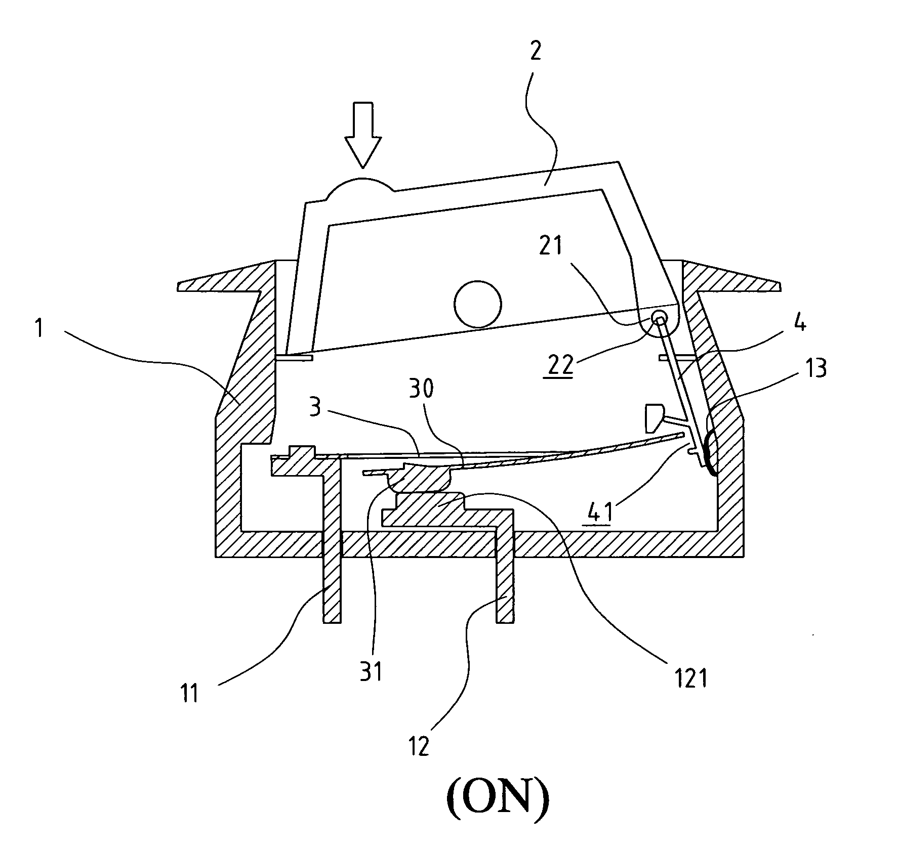
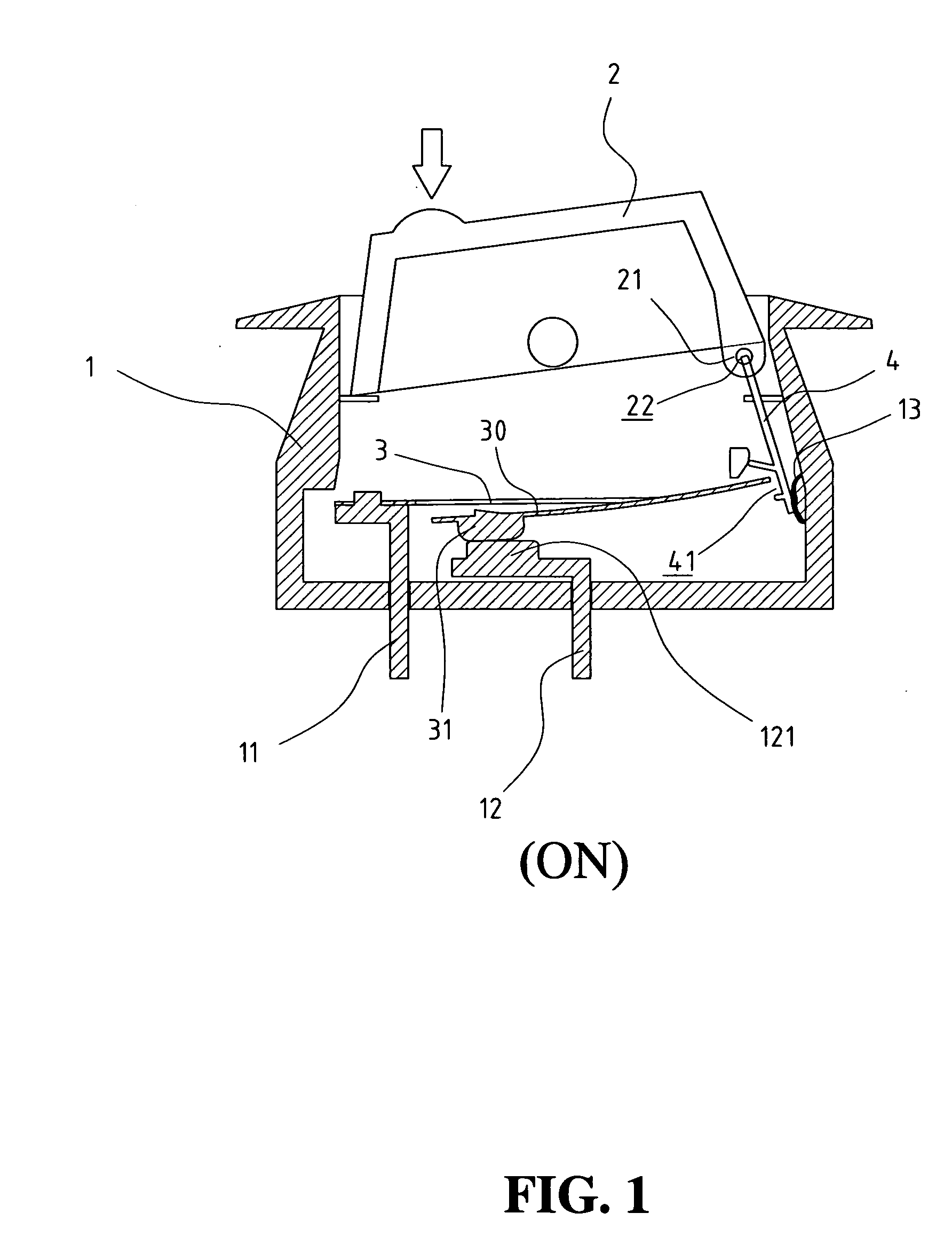
[0025] Referring to the drawings and in particular FIGS. 1 and 2, a switch device of the present invention comprises a case 1 having an open top and a switch member 2 is pivotably engaged with the open top of the case 1. A first terminal 11 and a second terminal 12 respectively extend through a bottom of the case 1. A bimetallic plate 3 as shown in FIG. 7 has a first end fixed to the first terminal 11 and a first contact point 31 is connected to a free end 30 of the bimetallic plate 3. The free end 30 is split from the bimetallic plate 3 and the first contact point 31 is connected to the free end 30. A second contact point 121 is connected to the second terminal 12 and located beneath the first contact point 31.

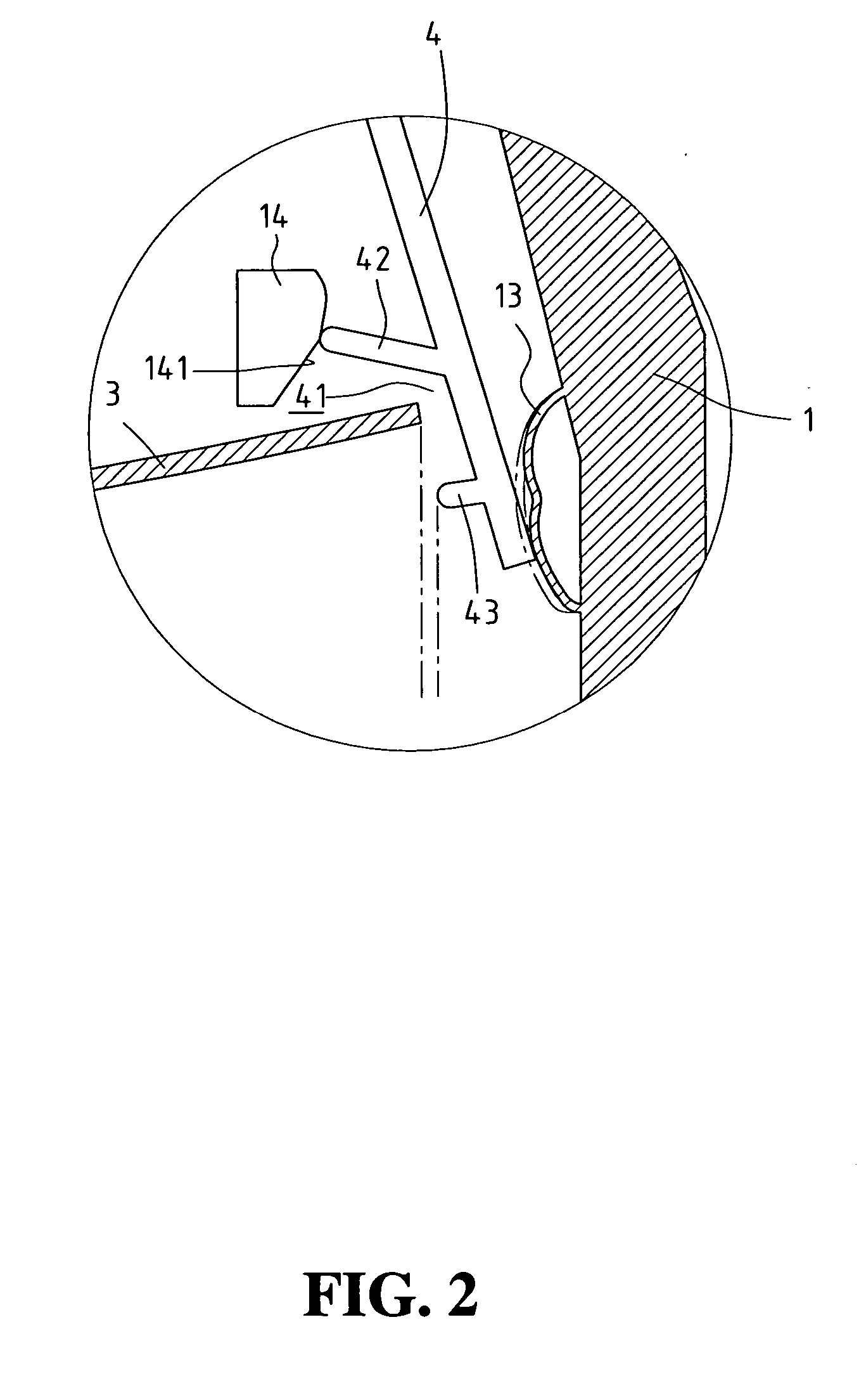
[0026] Further referring to FIG. 9, a hooking member 4 has a rod 41 extending laterally from a first end thereof and is inserted through a hole 22 defined through an extension plate 21 extending form an end of an underside of the switch member 2. A second end of the hooking ...


PUM


Abstract

A switch device includes a case with a switch member pivotally engaged with the open top of the case. Two terminals extend from a bottom of the case and a bimetallic plate has a first end fixed to one of the terminals. A distal end of the bimetallic plate is located above the other terminal. A hooking member has one end connected to the switch member and the other end has a hooking portion with which the distal end of the bimetallic plate is engaged. The distal end of the bimetallic plate is lifted when the switch member is pushed to “ON” position. The hook portion is defined between first and second boards and the second board located lower than the first board is shorter so that the bimetallic plate is allowed to be deformed without obstruction when the switch device is overloaded.

Description

FIELD OF THE INVENTION [0001] The present invention relates to a switch device that includes a hooking member connected to the switch member and the hooking member includes a short sidewall so as to allow the bimetallic plate in “ON” status to be deformed without obstruction when in overload. BACKGROUND OF THE INVENTION [0002] A conventional circuit breaker incorporates a fuse between a switch and the circuit such that when there is an electrical overload, the fuse will first melt before the overload causes damages. However, if the fuse is not properly installed or an improper fuse is used the overload current cannot melt the fuse and a disaster can be resulted. U.S. Pat. Nos. 5,262,748, 4,167,720, 4,937,548, 5,223,813, 5,451,729, and 5,558,211 all disclose different types of circuit breakers which commonly include a complicated mechanism to drive the bimetallic plate which is expected to be deformed and bent when overload in current. Nevertheless, it is noted that the bimetallic pl...

Claims


Application Information

Patent Timeline
Patent Type & Authority Applications(United States)
IPC IPC(8): H01H37/54H01H73/26
CPCH01H73/26
Inventor YU, TSUNG-MOU
Owner YU TSUNG MOU
Why Eureka
Try Eureka