Automatic slack adjuster assembly for vehicle braking system

a technology of automatic slack adjustment and vehicle braking system, which is applied in the direction of slack adjusters, axially engaging brakes, brake types, etc., can solve the problems of reducing the work efficiency of the brake shoe, the clearance between the brake shoe and the drum starts to get enlarged, and the friction lining wears along with the brake drum, so as to achieve easy adaptability

Inactive Publication Date: 2005-12-15
ANG AUTOMOTIVE IND
View PDF11 Cites 11 Cited by
  • Summary
  • Abstract
  • Description
  • Claims
  • Application Information

AI Technical Summary

Benefits of technology

[0019] Another object of the invention is to provide nearly constant free movement of the lever housing to a predetermined angular range within which the automatic mechanism remains dormant thereby avoiding over-adjustment.
[0020] Yet, another object of the present invention is to provide optimum clearance between brake lining and drum surface.
[0022] Another object of the present invention is easy adaptability, initial mounting and adjustment in the existing brake system without alteration.

Problems solved by technology

As the vehicles run, the brake is applied several times, which causes the wear of the friction lining of the brake shoes along with that of brake drum.
During course of time, the clearance between the brake shoes and drum starts getting enlarged due to this wear.
A situation may arise when the full air chamber stroke would fail to expand the brake shoes enough for effective braking.
This results in productive time loss.
Any negligence in getting the adjustment done in time may also cause accidents due to non-effective braking.
The brake adjustments are required to be done several times during the life of the brake linings, resulting in loss of several productive days.
Besides the effectiveness of braking may also get impaired if timely adjustments are not carried out.
In the prior art application use of clutches, gear trains secondary primary worms results in slack adjustment.
The system as described in the prior art is extremely complex and makes the system cumbersome.
The complexity of the system makes the prior art system extremely difficult to implement with reduced efficiency of the system as a whole.
Such prior devices had certain disadvantages as mentioned below: Higher cost Too bulky and needs modifications for fitment or need external anchoring bracket with a chassis.
Use too many parts and miniature clutch systems which tend the wear out and malfunction.
The certain devices could not be sealed properly against ingress of water / water mists and dust thereby rendering the parts to wear and seize.
Some devices are not interchangeable for left and right side application and the direction of thrust.

Method used


Image

  • Automatic slack adjuster assembly for vehicle braking system
  • Automatic slack adjuster assembly for vehicle braking system
  • Automatic slack adjuster assembly for vehicle braking system

Examples


Embodiment Construction

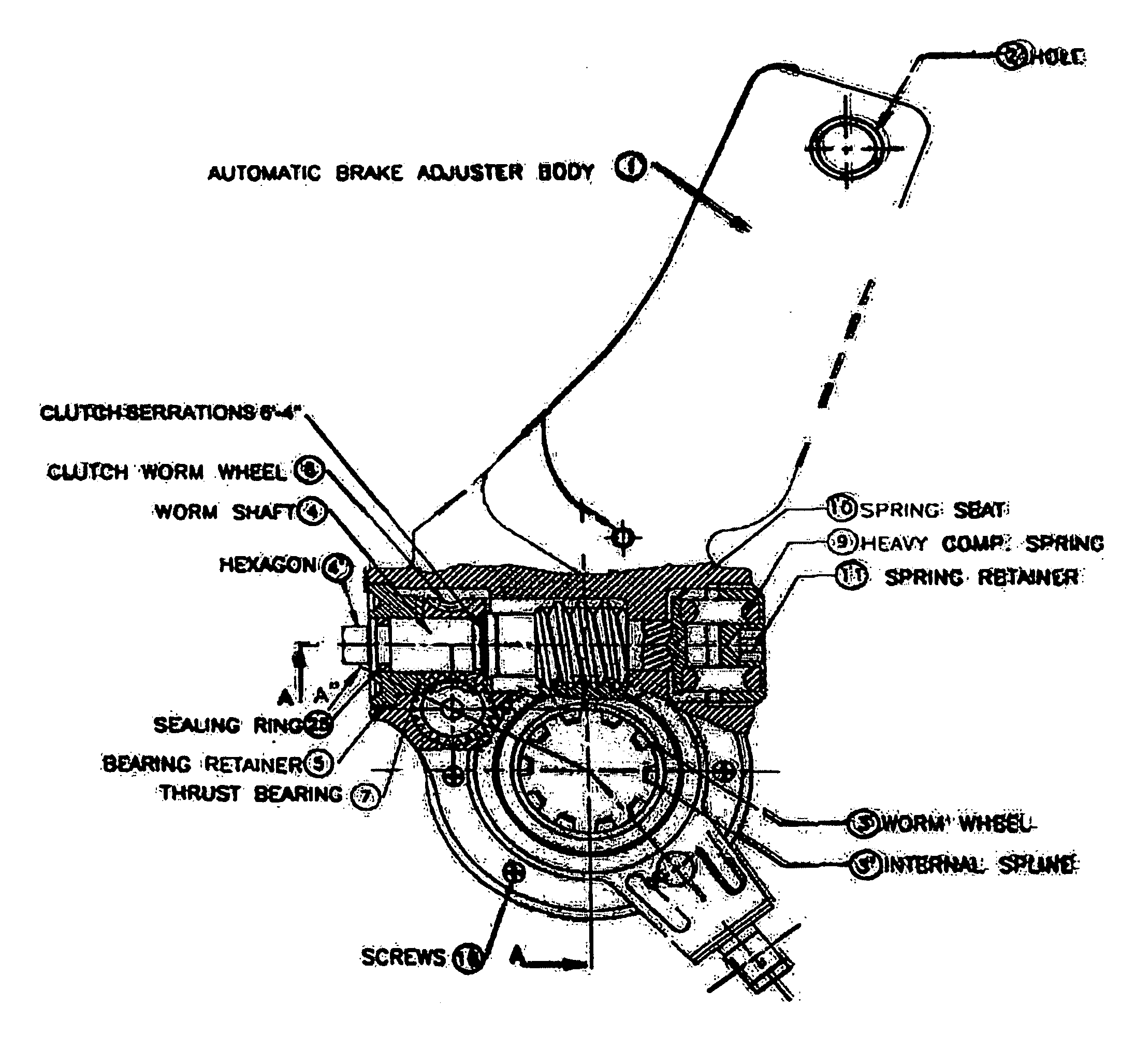
[0031] Accordingly, the present invention relates to slack adjuster, which automatically adjusts the slack between the brake drum and the brake lining riveted to the brake shoes. The said brake shoes expand with the rotation of the S-profiled cam.

[0032] In FIG. 6, the said automatic slack adjuster assembly for vehicle braking system comprises of [0033] (a) a lever housing (1) accommodating a worm-wheel means having splined bore to receive camshaft, said worm-wheel means comprising a worm in functional relationship with a wheel (3); [0034] (b) a worm shaft (4) having ratchet cylinder (5) portion, enmeshed in said worm at right angle to the axis of the wheel; [0035] (c) a paul (6) positioned over the ratchet cylinder (5) portion of the worm shaft (4) inside a machined guideway in the housing (1); [0036] (d) a leaf spring (10) located on one end of the machined guideway pressing down the said paul; [0037] (e) an actuator rod (7) linked to the said paul (6) runs inside guide (9), oppos...


PUM


Abstract

The invention pertains to the fluid powered brake systems of vehicles using brake drum and lined brake shoes internally expanded by cam. The invented device automatically adjusts the slack, which develops due to the wearing of brake liners and the drum. The device is depicted in FIG. 1 when the angular movement of the Lever Housing (1) exceeds the desired limit due to the wear, the internal device adjusts the excess clearance of slack automatically. The parts consist of Worm Wheel (3); an enmeshing Worm Shaft (4); a Paul (6); a Leaf Spring (1); a Ratchet cylinder (5); an Acuator Rod (7); a Guide (9); an End Connector (8); a Clevis (2); and Clevis Pins (2A) and 2(B). When brakes are applied the Actuator Rod (7) gets pulled out and brings the Paul (6) in engagement with Ratchet cylinder (5). On the return stroke the Paul (4) rotates the worm shaft (4) which in turn rotates the worm wheel (3) and the attached cam thereby removing the slack.

Description

FIELD OF INVENTION [0001] The present invention relates to a vehicle braking system and more particularly to an automatic slack adjusting assembly of novel construction and mode of operation, which actuates the cam for brake application in fluid operated brakes of medium and heavy vehicles. The novel aspect of the present invention adjusts the slack automatically, yet does not affect the provision of manual adjustment of the braking parts. BACKGROUND AND PRIOR ART REFERENCES [0002] The invention pertains to pneumatically powered brake system of medium and heavy vehicles. These vehicles invariably use internally expandable brake shoes lined with friction material and the braking effect is produced when these shoes make contact with a drum mounted on the driving or trailing wheels. The expansion of the brake shoes is done by S-profiled cams, which push the shoes out when the cam is rotated. The cam is rotated by lever arm at the end of which the force is applied by an air chamber, whi...

Claims


Application Information

Patent Timeline
Patent Type & Authority Applications(United States)
IPC IPC(8): F16D55/02F16D65/60
CPCF16D65/60
Inventor CHADHA, PREMJIT SINGHCHOUDHARY, NIRMAL BHAGAT
Owner ANG AUTOMOTIVE IND
Why Eureka
Try Eureka