

Nunchaku
a technology of nunchaku and nepa, which is applied in the field of nunchaku, can solve the problems of unexpected and dangerous separation of the baton b>5, and achieve the effect of effectively preventing the whole joint pin
- Summary
- Abstract
- Description
- Claims
- Application Information
AI Technical Summary
Benefits of technology
Problems solved by technology
Method used
Image

Examples
Embodiment Construction
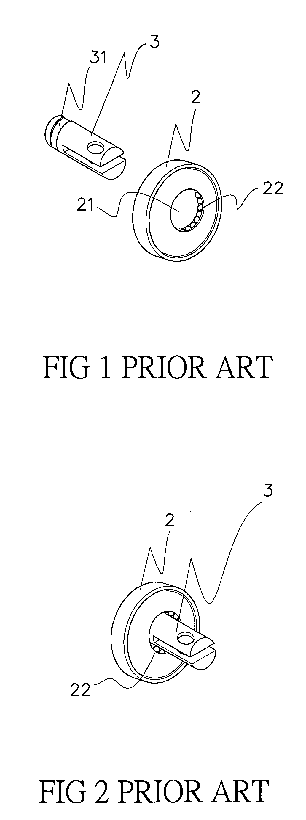
[0016] Please refer to FIG. 9 that shows a nunchaku according to the present invention. As shown, the nunchaku includes two batons 5 connected end to end via a chain 1. Each of the two batons 5 is connected at an inner end to an end of the chain 1 via a bearing 2 mounted inside the inner end of the baton 5 and a joint pin 4 rotatably connected to the bearing 2 and projected from the inner end of the baton 5.
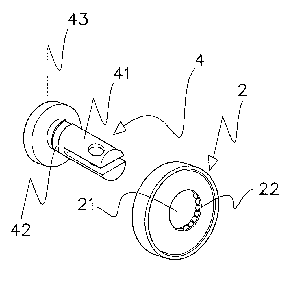
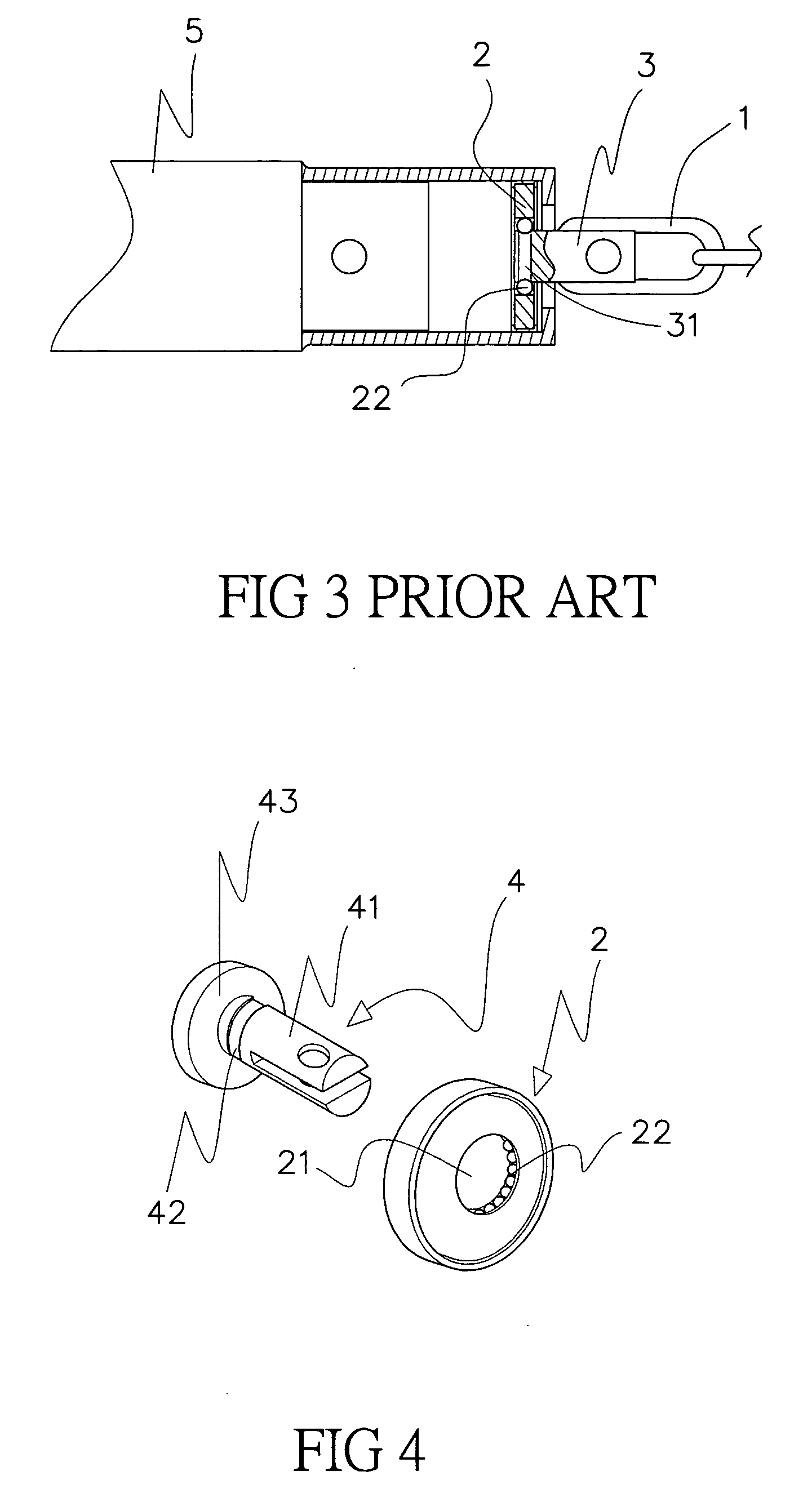
[0017] Please refer to FIGS. 4, 5, and 6 at the same time. The joint pin 4 includes a front section 41, an annular groove 42 provided near a rear part of the front section 41, and a circular flange 43 provided at a rear end of the joint pin 4 close to the annular groove 42. The bearing 2 has an inner bore 21 close to an outer diameter of the front section 41 of the joint pin 4, so that the front section 41 of the joint pin 4 could be extended through the inner bore 21 of the bearing 2 to project from the inner end of the baton 5 with the flange 43 abutted on an inner side of the...
PUM
 Abstract
Description
Claims
Application Information