Dual area piston for transmission clutch and sequential control therefor

Inactive Publication Date: 2006-03-16
FORD GLOBAL TECH LLC
View PDF13 Cites 27 Cited by
  • Summary
  • Abstract
  • Description
  • Claims
  • Application Information

AI Technical Summary

Benefits of technology

[0008] The invention relates to a single low/reverse clutch piston with two distinct areas, which create distinct static and dynamic clutch gains. This invention provides direct control of the pressurized state of the secondary

Problems solved by technology

This high gain requirement, howev

Method used


Image

  • Dual area piston for transmission clutch and sequential control therefor
  • Dual area piston for transmission clutch and sequential control therefor
  • Dual area piston for transmission clutch and sequential control therefor

Examples


Embodiment Construction

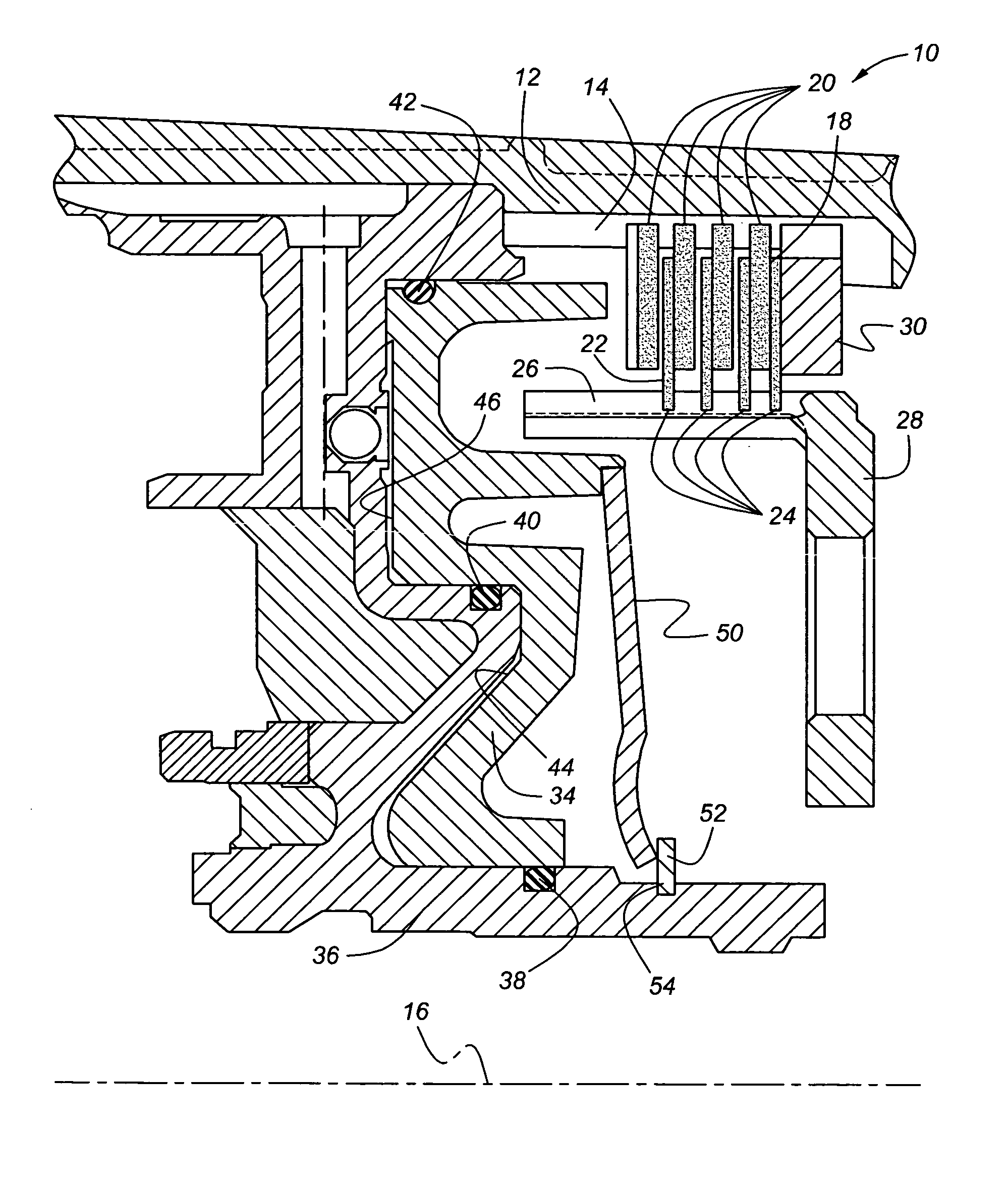
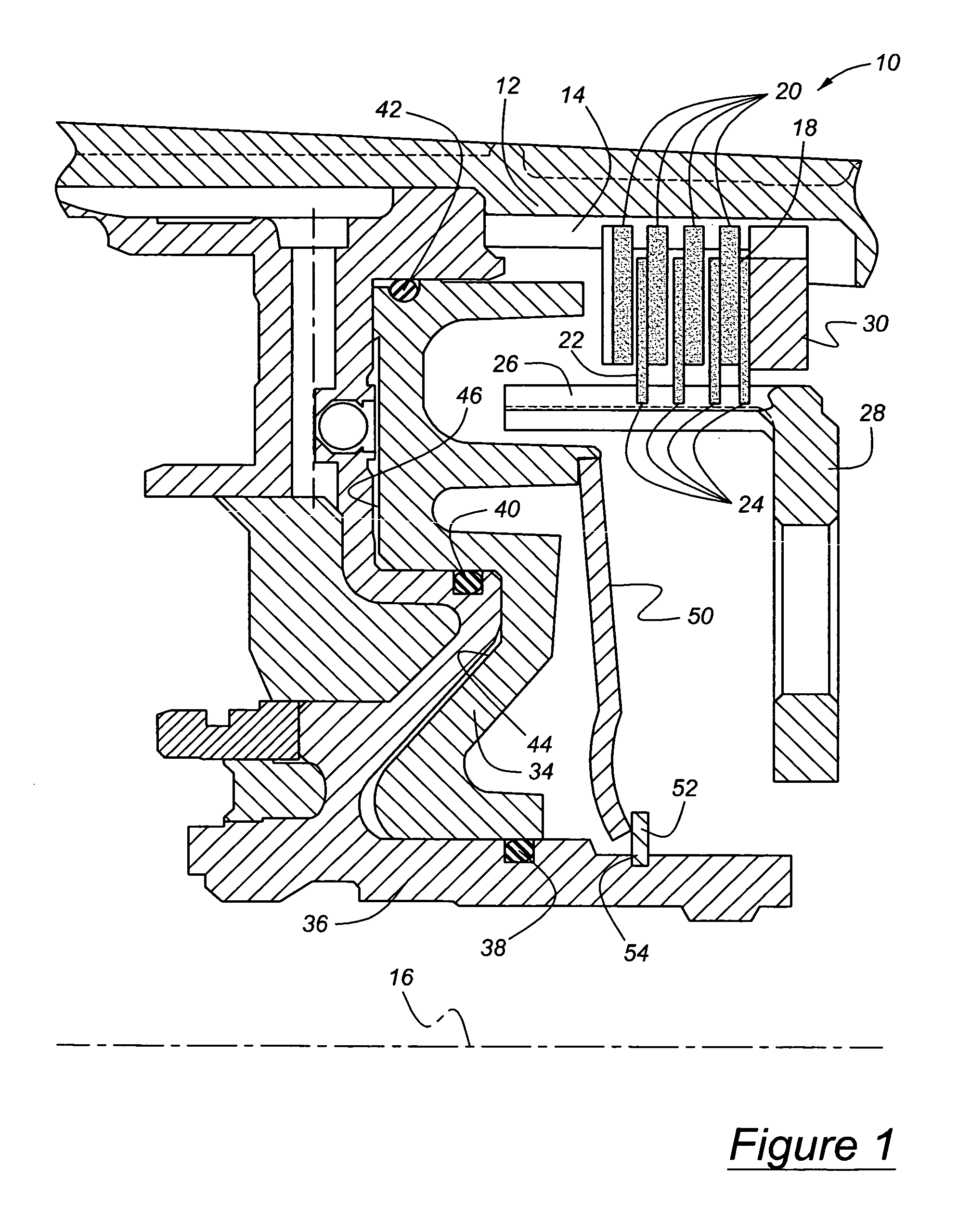
[0018] Referring now to the drawings, there is illustrated in FIG. 1 a hydraulically actuated friction clutch 10, preferably the low / reverse clutch of an automatic transmission, which is located in a transmission housing. A connecting member 12, secured to and rotating with a component of a planetary gear set, having an inner surface on which spline teeth 14, directed parallel to an axis 16, are formed. The clutch is arranged substantially symmetrically about axis 16. Pressure plates 18, spaced mutually along the axis 16, have teeth 20 located at a radially outer periphery and engaging the spline teeth 14. Located between each pressure plate 18 is a clutch disc 22 having teeth 24 located at a radially inner periphery and engaging axially directed spline teeth 26 formed on a member connecting 28, which is secured to and rotates with another component of a planetary gearset. A backing plate 30, similarly splined to the internal splines 14, is secure to the housing against displacement...


PUM


Abstract

A system for actuating a clutch that alternately driveably connects and disconnects components, includes a clutch having a piston that includes a first apply area and a second apply area, a fluid pressure source, a source of variable control pressure, and a control coupled with the fluid pressure source and operative in response to the control pressure to engage the clutch initially by increasing pressure steadily at the first apply area up to a first magnitude followed by a rapid increase in pressure at the first apply area and the second apply area above the first magnitude to a second magnitude.

Description

BACKGROUND OF THE INVENTION [0001] This invention relates to a friction control element, such as a hydraulically or pneumatically actuated clutch, of the type used to control operation of an automatic transmission. In particular, the invention pertains to a control for producing staged engagement and disengagement of such a clutch having at least two sealed areas on its actuating piston. [0002] Automatic transmissions are typically designed to transmit full engine torque and the engine torque as amplified by a torque converter at stall torque under static. i.e., non-shifting conditions. The control system of an automatic transmission includes a low / reverse clutch, which is applied or engaged to produce the lowest forward speed ratio and the reverse drive speed ratio. Such engagement produces a drive connection between components of the planetary gearing, which when selectively combined with the engagement of other control elements, results in the transmission operating in low gear o...

Claims


Application Information

Patent Timeline
IPC IPC(8): F16D25/0638F16D25/12
CPCF16D25/0638F16D2048/0212F16D48/02
Inventor BISHOP, BRIANBEZJAK, PETEJUNGBLUTH, KARL
Owner FORD GLOBAL TECH LLC
Why Eureka
Try Eureka