

Visual database modeling
a database and visual technology, applied in computing, electric digital data processing, instruments, etc., can solve problems such as processing that can take several weeks, and achieve the effect of keeping the complexity of the configuration operation small
- Summary
- Abstract
- Description
- Claims
- Application Information
AI Technical Summary
Benefits of technology
Problems solved by technology
Method used
Image

Examples
example migration
[0229] Example Migration
[0230]FIGS. 24-29 illustrate an example migration using the above-described techniques and visual modeling tools.
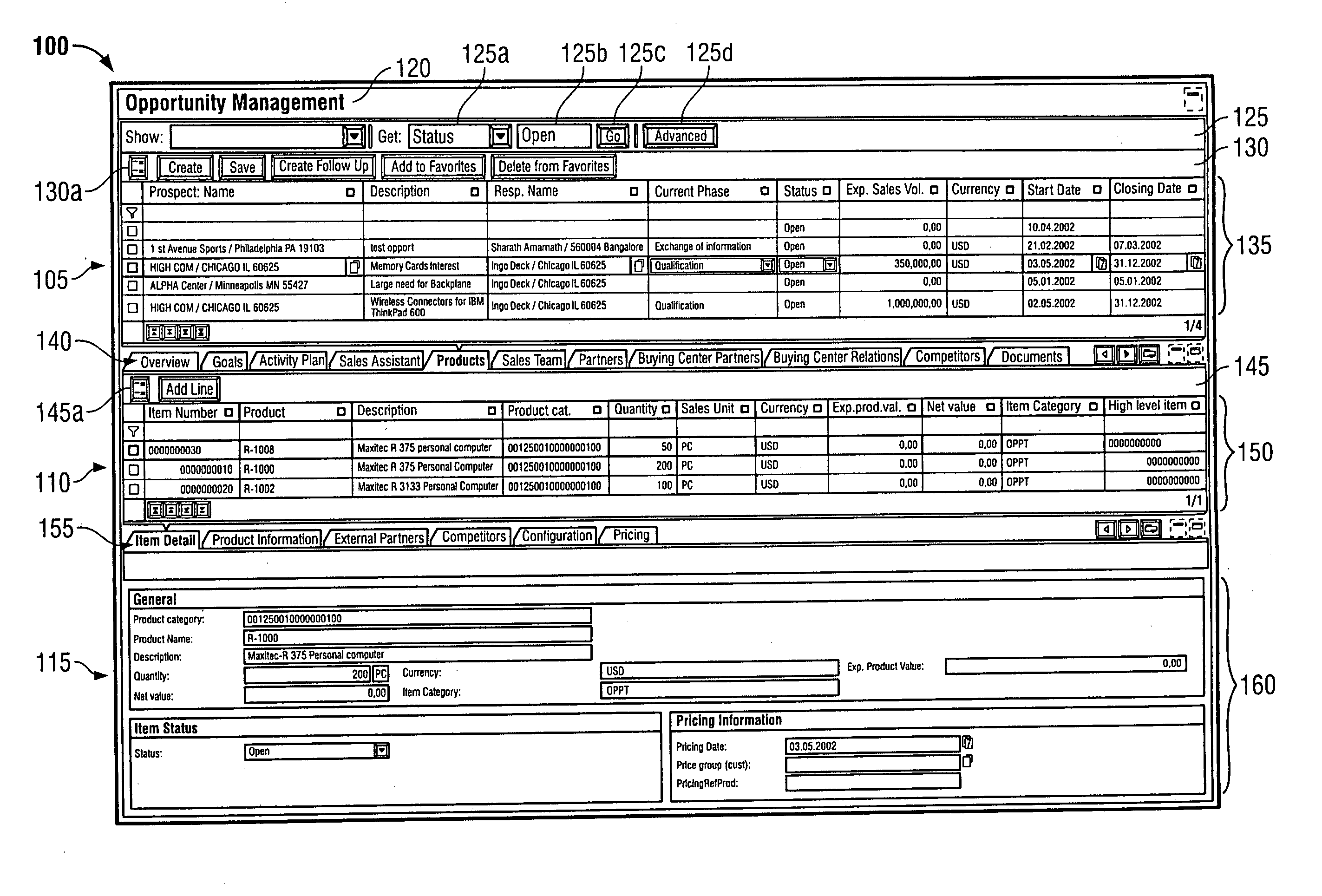
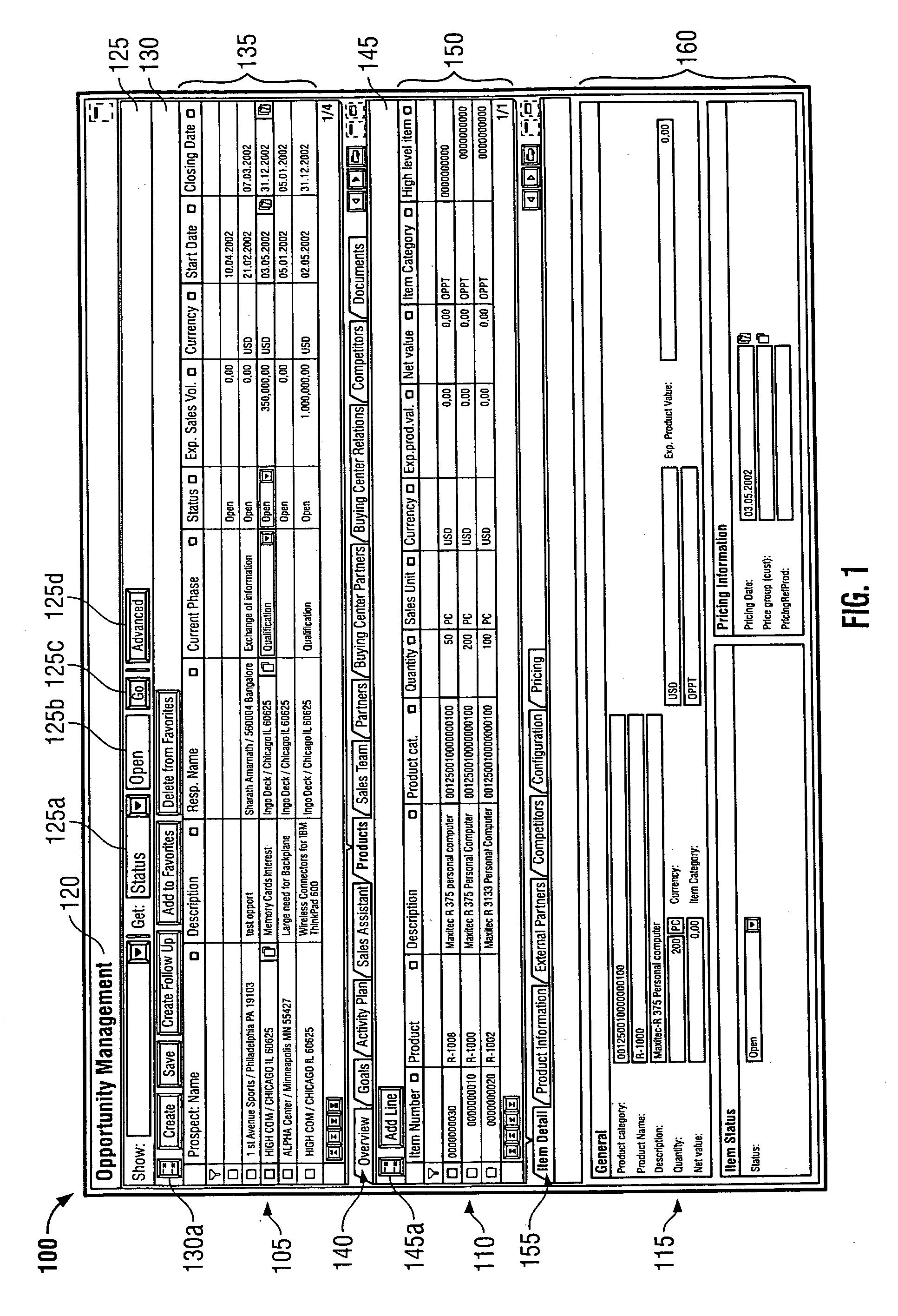
[0231]FIG. 24 shows an application 2400 to be migrated. As described above, a developer determines the functionality of the application to be migrated and then selects one or more patterns based on this determination. In this case, the application is used to search for products offered by a particular supplier (identified in a supplier input form 2410). The results of a product search is shown in a results window 2420.
[0232] As shown in FIG. 25, the developer selects an OIP pattern 2500 using a graphical configuration tool. The developer will then configure the OIP pattern 2500 so that it provides the same or similar functionality as the application 2400. More specifically, the OIP pattern 2500 will be configured to execute a similar query into the application database, and to display similar results retrieved from the application database.
[0233...
PUM
 Abstract
Description
Claims
Application Information