
Bending device and method for bending a plate
a technology of bending device and plate, which is applied in the direction of blade accessories, machines/engines, waterborne vessels, etc., can solve the problems of inability to ensure defined and reproducible bending over at a series of plates, comparatively long fitting time of manual activity, and comparatively high risk of injury to the fitter and/or the blade of the compressor. to achieve the effect of more effective bending operation
- Summary
- Abstract
- Description
- Claims
- Application Information
AI Technical Summary
Benefits of technology
Problems solved by technology
Method used
Image

Examples
Embodiment Construction
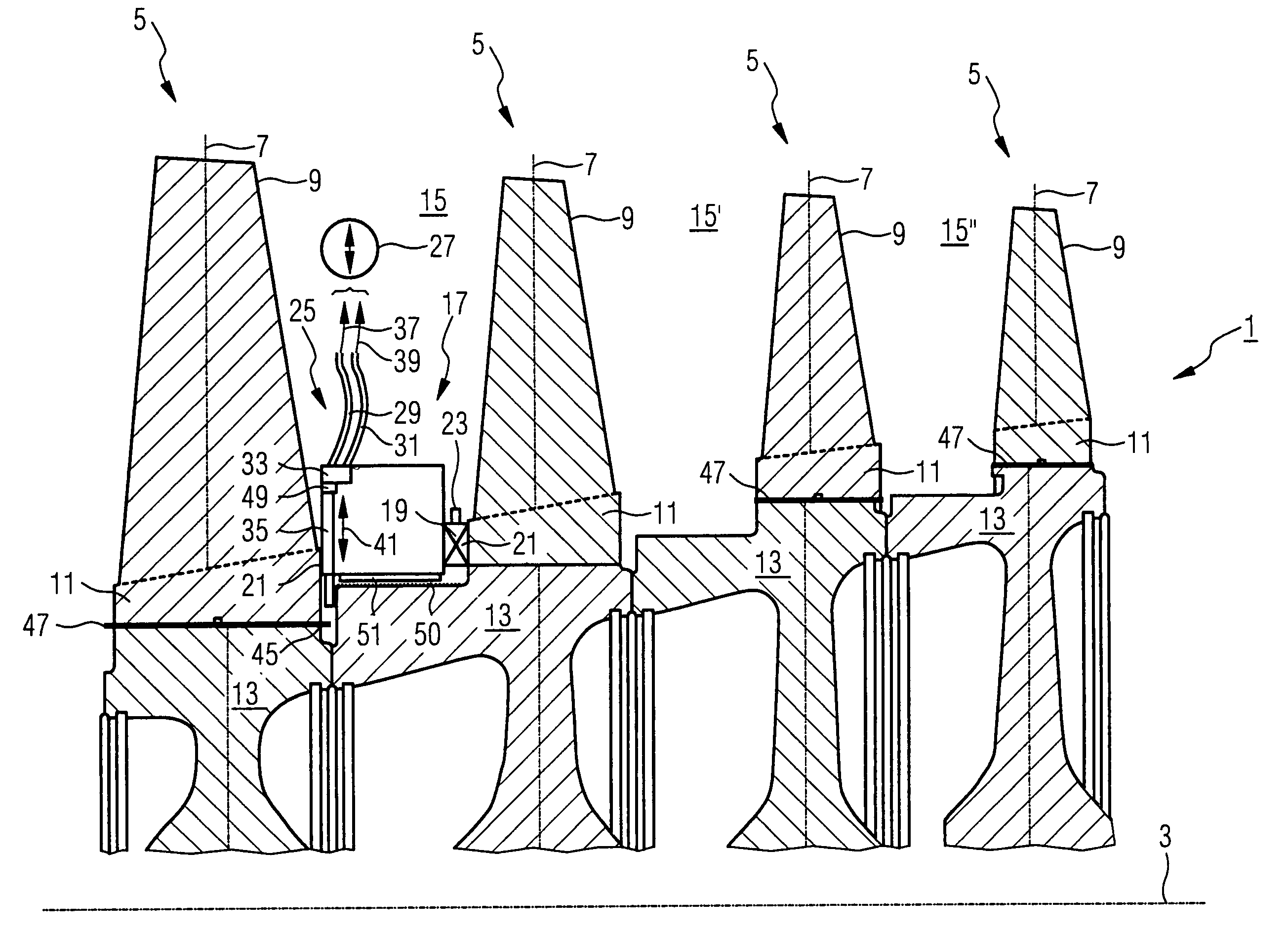
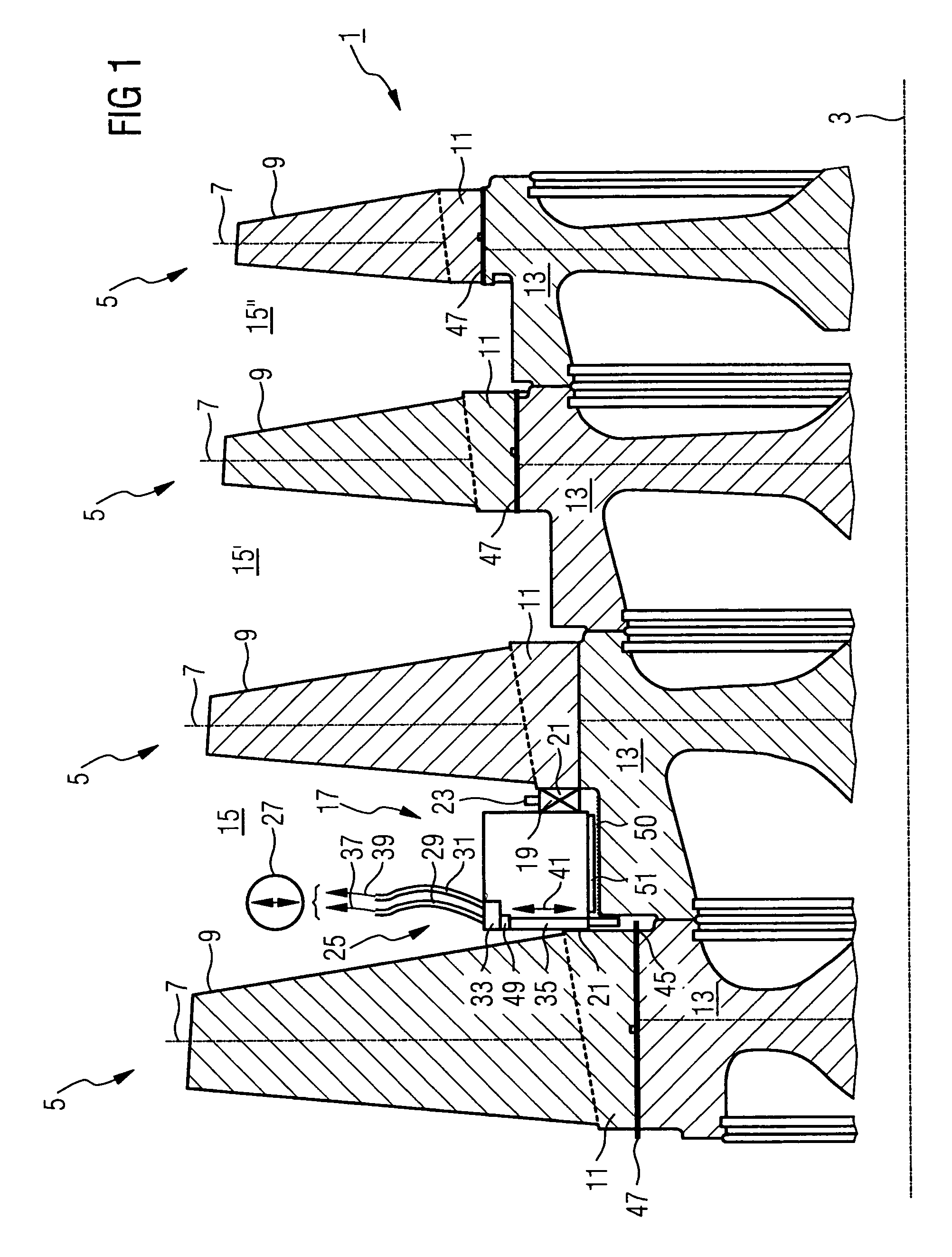
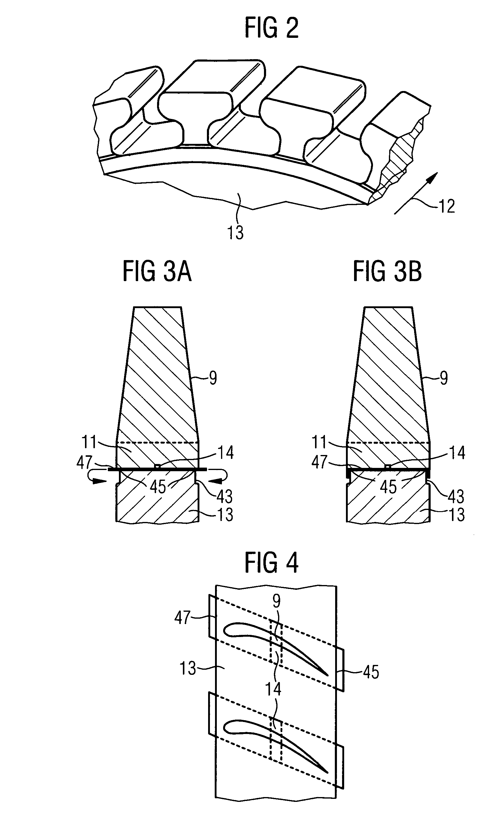
[0037]FIG. 1 shows an impeller 1 of a compressor (not shown in any more detail) having a number of blade rings 5 arranged along an axis 3 of the compressor. A blade ring 5 here has a number of blades 9 which extend along a radius 7 and of which in each case one blade 9 is shown in section. A blade 9 of the compressor is in this case held with its root 11, in a similar manner as in a tongue-and-groove joint, on a respective segment 13 of the compressor wheel 1. Here, the groove for locating the root 11 is designed in each case as an axial groove. The orientation and configuration of such locating grooves is shown by way of example in FIG. 2, the arrow 12 indicating the direction of the turbine axis 3. During the fitting of the blade 9 on the impeller 1, the root 11 together with the plate 47 placed underneath is pushed into the groove of the segment 13.
[0038]As can be seen in the detailed illustration in FIG. 3A, the plate 47 is provided with a bead 14 in the circumferential directio...
PUM
| Property | Measurement | Unit |
|---|---|---|
| radius | aaaaa | aaaaa |
| force | aaaaa | aaaaa |
| power | aaaaa | aaaaa |
Abstract
Description
Claims
Application Information