Bending device and method for bending a plate

a technology of bending device and plate, which is applied in the direction of forging/pressing/hammering apparatus, machines/engines, forging presses, etc., can solve the problems of inability to ensure defined and reproducible bending over at a series of plates, comparatively long fitting time of manual activity, and comparatively high risk of injury to the fitter and/or the blade of the compressor to be damaged, so as to achieve more effective bending operation.

Active Publication Date: 2006-09-21
SIEMENS ENERGY GLOBAL GMBH & CO KG
View PDF12 Cites 11 Cited by
  • Summary
  • Abstract
  • Description
  • Claims
  • Application Information

AI Technical Summary

Benefits of technology

[0011] This is where the invention comes in, the object of which is to specify a device and a method for bending a plate in an intermediate space between two blade rings arranged along an axis of a compressor or a turbine and having blades extending along a radius, said device and method at the same time configuring the bending operation more effectively and also more reliably than in the case of a manual bending operation.

Problems solved by technology

Of course, on account of the manual activity, defined and reproducible bending-over at a series of plates cannot be ensured.
There is also the fact that the manual activity leads to a comparatively long fitting time.
The lever forces to be applied are partly so high that, if the lever slips off, there is a comparatively high risk of injury to the fitter and / or a blade of the compressor may be damaged.
The impeller or the wheel disk provided for accommodating the blades may also be damaged.
In addition, cracks may be initiated in the plate due to undefined, manual bending-over, which cracks may possibly impair the service life and reliable functioning of said plate.

Method used


Image

  • Bending device and method for bending a plate
  • Bending device and method for bending a plate
  • Bending device and method for bending a plate

Examples


Embodiment Construction

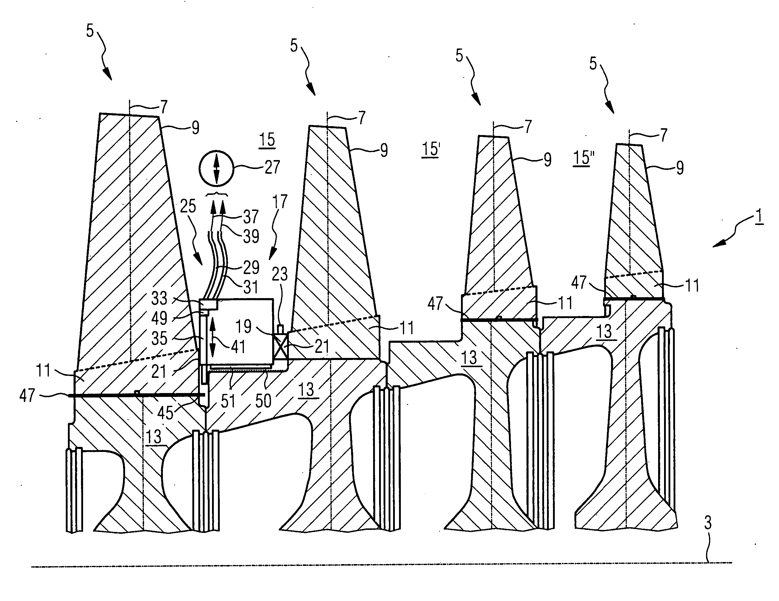
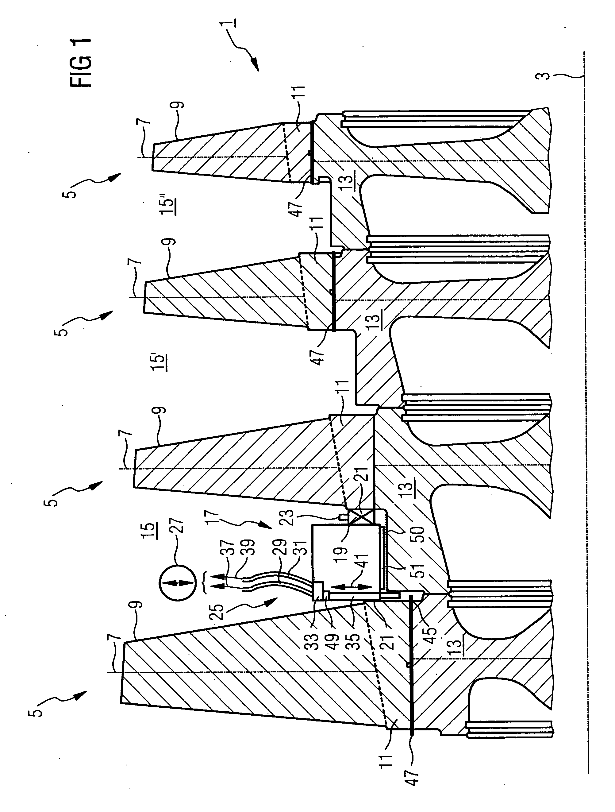
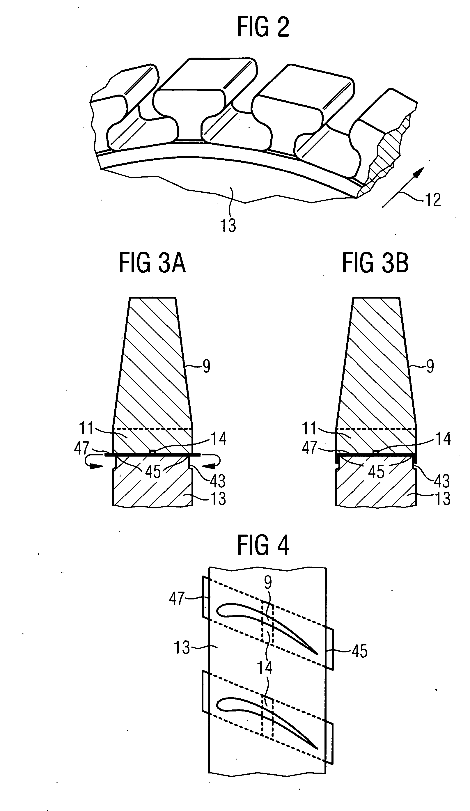
[0037]FIG. 1 shows an impeller 1 of a compressor (not shown in any more detail) having a number of blade rings 5 arranged along an axis 3 of the compressor. A blade ring 5 here has a number of blades 9 which extend along a radius 7 and of which in each case one blade 9 is shown in section. A blade 9 of the compressor is in this case held with its root 11, in a similar manner as in a tongue-and-groove joint, on a respective segment 13 of the compressor wheel 1. Here, the groove for locating the root 11 is designed in each case as an axial groove. The orientation and configuration of such locating grooves is shown by way of example in FIG. 2, the arrow 12 indicating the direction of the turbine axis 3. During the fitting of the blade 9 on the impeller 1, the root 11 together with the plate 47 placed underneath is pushed into the groove of the segment 13.

[0038] As can be seen in the detailed illustration in FIG. 3A, the plate 47 is provided with a bead 14 in the circumferential direct...


PUM

PropertyMeasurementUnit
radiusaaaaaaaaaa
forceaaaaaaaaaa
poweraaaaaaaaaa

Abstract

In order to configure the bending of a plate in an intermediate space between two blade rings, arranged along an axis of a compressor and having blades extending along a radius in a simpler and more effective manner, the novel concept provides a bending device which can be positioned in the intermediate space and has, according to the invention, a fixing element for the bending device, a hydraulic system and a punch which can be actuated by the hydraulic system. Accordingly, a method for bending a plate in the intermediate space provides for a bending device to be positioned in the intermediate space, for the bending device to be fixed in the intermediate space, and for a punch of the bending device to be hydraulically actuated for bending the plate, the punch being moved toward the plate to be bent, and the plate being bent under the effect of the punch.

Description

CROSS REFERENCE TO RELATED APPLICATIONS [0001] This application claims the benefits of European Patent application No. 05005872.6 filed Mar. 17, 2005, and is incorporated by reference herein in its entirety. FIELD OF THE INVENTION [0002] The invention relates to a bending device which can be positioned for bending a plate in an intermediate space between two blade rings arranged along an axis of a compressor or a turbine and having blades extending along a radius. The invention also relates to a method for bending a plate in the intermediate space. BACKGROUND OF THE INVENTION [0003] In a turbine or a compressor, a flow of working medium is admitted to a flow duct formed between a casing and an impeller or rotor. In this case, the flow duct extends along an axis of the compressor or turbine. Blades which are subjected to the flow of the working medium extend along a radius in the flow duct. These blades may be guide blades fastened to the casing or moving blades fastened to the impel...

Claims


Application Information

Patent Timeline
Patent Type & Authority Applications(United States)
IPC IPC(8): B21J9/18
CPCF01D5/30F05D2230/60Y10T29/49815Y10T29/4932Y10T29/49321F05D2260/30
Inventor MIOSGA, DAVIDSCHRODER, PETER
Owner SIEMENS ENERGY GLOBAL GMBH & CO KG
Why Eureka
Try Eureka