
Article transport facility

a technology for transporting facilities and articles, applied in transportation and packaging, elevators, ways, etc., can solve the problems of complex facility design work, time-consuming and laborious work, and difficulty in improving article transport efficiency, and achieve the effect of changing the attitude portion

Active Publication Date: 2014-04-22
DAIFUKU CO LTD
View PDF15 Cites 10 Cited by
  • Summary
  • Abstract
  • Description
  • Claims
  • Application Information

AI Technical Summary

Benefits of technology

This configuration simplifies facility design and improves transport efficiency by allowing for more direct routes and reduced low-speed sections, enhancing the overall efficiency of article transport.

Problems solved by technology

Because the first diverging path and the second diverging path are provided at different locations in the longitudinal direction of the pair of the adjacent travel paths in plan view in the article transport facility of Patent Document 1, there is a disadvantage that the facility designing work, in which the arrangement of the facility is finalized while determining the locations at which the first diverging path and the second diverging path should be installed, is complicated, in addition to a disadvantage that it is difficult to improve article transporting efficiency; thus there is a desire for improvements.
During this process, the work involved in determining the installing locations of the first diverging path and the second diverging path while taking various possible travel routes into consideration is done by comparing the case in which the first diverging path is installed with the case in which the second diverging path is installed at each location of the pair of travel paths; thus, the work was time consuming and painstaking.
Thus, there was a disadvantage that the facility designing work was complicated.
Even in such a case, if the specific section is too short, it is difficult to improve the article transporting efficiency because only one of the first diverging path and the second diverging path can be provided.
As a result, even when the first diverging path and the second diverging path can be provided in one specific section, it is difficult to improve article transporting efficiency.

Method used


Image

  • Article transport facility
  • Article transport facility
  • Article transport facility

Examples


first embodiment

[First Embodiment]

[0128]The first embodiment of an article transport facility of the ceiling installation type in accordance with the present invention is described next with reference to the drawings.

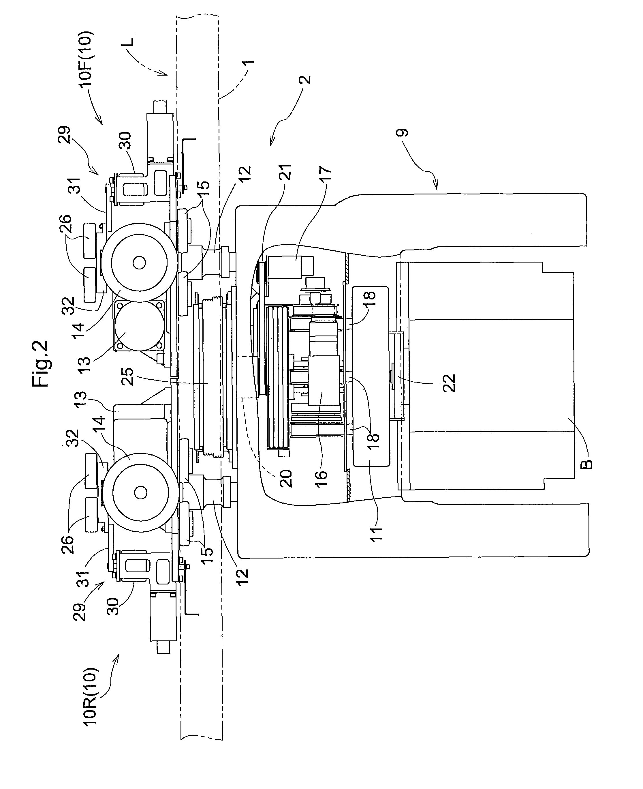
[0129]As shown in FIGS. 2-4, a travel guide member L including guide rails 1 is provided on the ceiling side (on the ceiling side of a clean room in the present example). And article transport vehicles 2 each of which is configured to travel along the travel guide member L is provided.

[0130]In the present embodiment, each article transport vehicle 2 is configured to transport, as an article B, a container for housing or carrying semiconductor substrates.

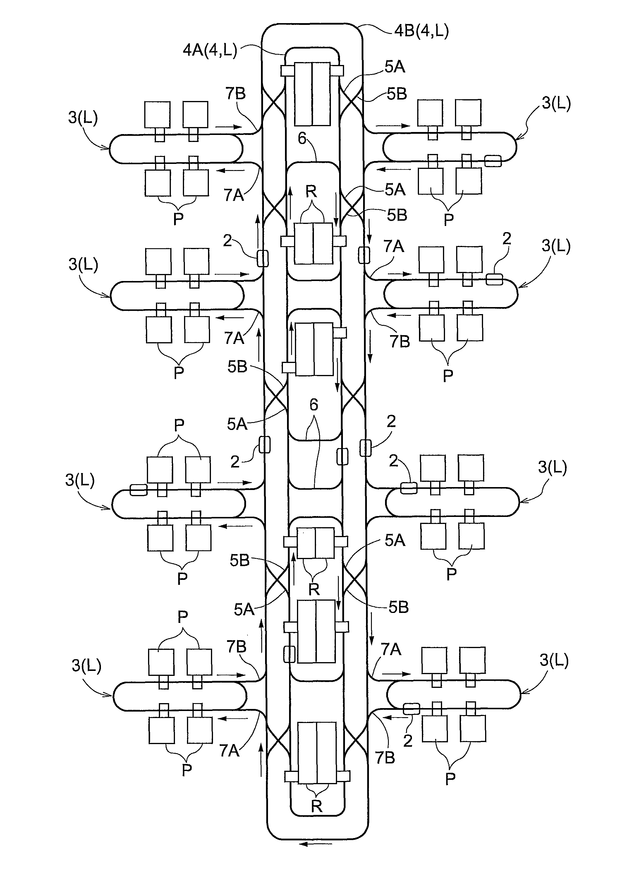
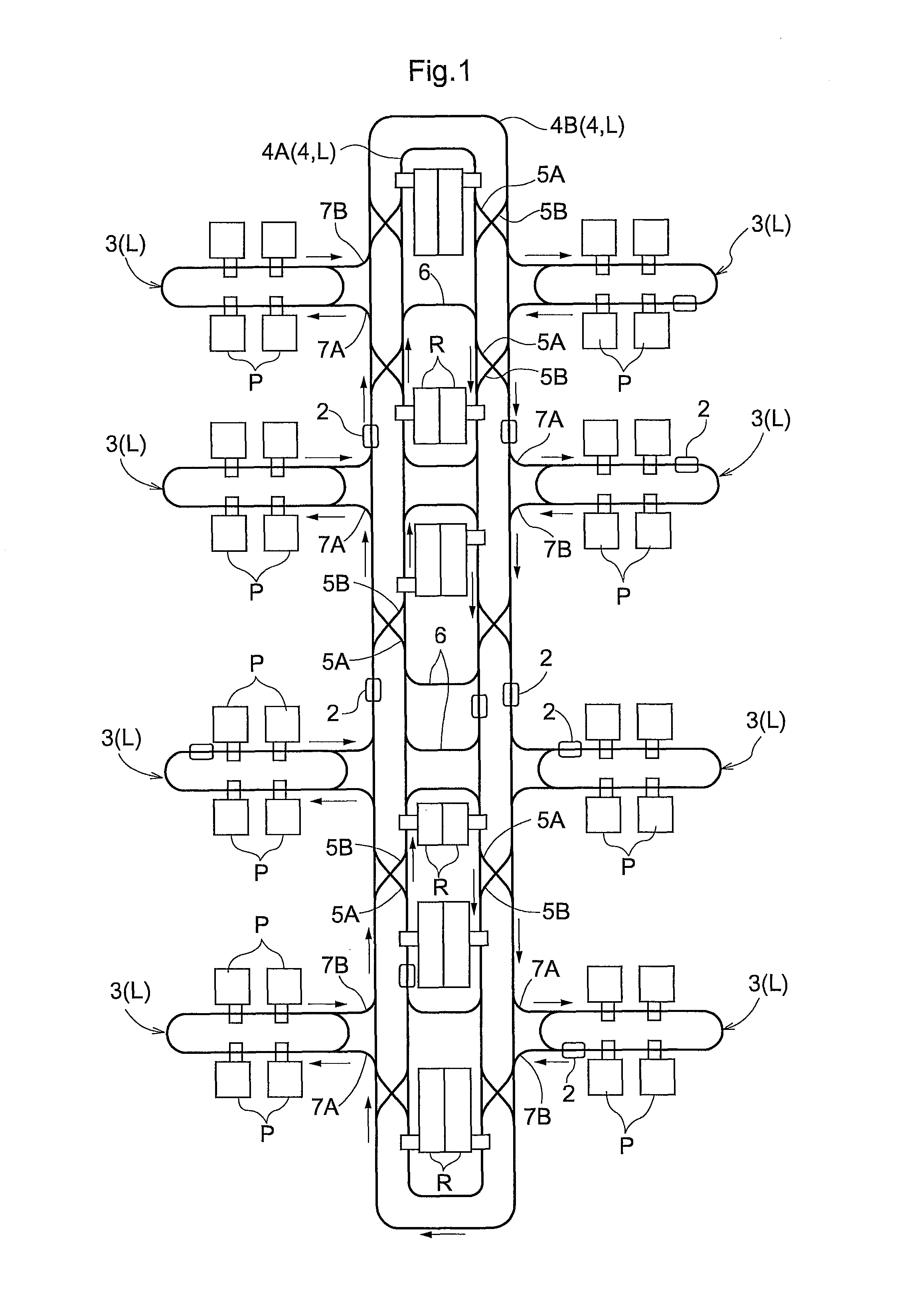
[0131]As shown in FIG. 1, the travel guide member L defines or forms a plurality of travel paths 4 for the article transport vehicles 2 and also defines diverging paths 5A, 5B for connecting different travel paths 4 to each other. In the present embodiment, the travel guide member L further defines or forms a plurality of loop-shaped se...

second embodiment

[Second Embodiment]

[0223]The second embodiment is described next. This second embodiment has a configuration that is similar to that in the first embodiment except that the configuration for operating the pair of movable rails 35 differs from that in the first embodiment.

[0224]Accordingly, in order to avoid duplicating the descriptions, only the configuration for operating the pair of movable rails 35 is described.

[0225]The second embodiment is identical to the first embodiment in that the first guide body 37 is attached to the rail support frame 36 and that the relay link 39 is supported by the first movable body 38 which is guided and supported by the first guide body 37. Also identical to the first embodiment is the fact that the second guide body 43 is provided in the undersurface of the movable rail 35, that the second movable body 44 which is movably guided and supported by the second guide body 43 is rotatably supported by the bearing 45 attached to the rail support frame 36,...

third embodiment

[Third Embodiment]

[0232]The third embodiment is described next. This third embodiment has the configuration that is identical to that of the first embodiment except that the configuration of the pair of movable rails 35 is different, that the configuration of the attitude changing portion 28A in the upper guide rail 28 is different, and that the configurations for operation of the pair of movable rails 35 and the attitude changing portion 28A of the upper guide rail 28 are different.

[0233]Therefore, in order to avoid duplicating the descriptions, only the features that are different from those in the first embodiment are described below, and description of the features that are identical to those in the first embodiment are omitted.

[0234]The third embodiment is identical to the first embodiment in that the pair of movable rails 35 are configured to be able to change the arrangement of the movable rails 35 between the first diverging path forming state (see FIG. 23) in which the firs...


PUM


Abstract

A travel guide member which forms travel paths for an article transport vehicle is provided on a ceiling side. The travel guide member defines a plurality of travel paths along which the article transport vehicle travels in the same direction such that the travel paths are spaced apart from each other in a path lateral direction and defines a first diverging path and a second diverging path for connecting with each other a first travel path that is one of a pair of adjacent travel paths among the plurality of the travel paths and a second travel path that is the other of the pair of the adjacent travel paths. The first diverging path and the second diverging path are formed such that both extend in directions that are slanted with respect to the travel path in plan view and such that they intersect each other in plan view.

Description

FIELD OF THE INVENTION[0001]The present invention relates to an article transport facility in which a travel guide member is provided on a ceiling side for defining travel paths for an article transport vehicle and in which the travel guide member defines a plurality of the travel paths along which the article transport vehicle travels in the same direction such that the travel paths are spaced apart from each other in a path lateral direction, and defines a first diverging path and a second diverging path for connecting, with each other, a first travel path that is one of a pair of adjacent travel paths among the plurality of the travel paths and a second travel path that is the other of the pair of the adjacent travel paths.BACKGROUND[0002]Article transport facilities such as one described above are installed, for example, in a ceiling area in a clean room, and are used to transport, as articles, containers for housing substrates, such as silicon substrates.[0003]More specifically...

Claims


Application Information

Patent Timeline
Patent Type & Authority Patents(United States)
IPC IPC(8): B66B3/00
CPCB66B3/00H01L21/67733H01L21/67715B65G35/06H01L21/67706
Inventor OGAWA, DAISUKESHIBATA, SUGURUOTANI, ATSUSHIKINUGAWA, TOMOTAKA
Owner DAIFUKU CO LTD
Learn More