Illumination device

a technology of a light guide and an end surface, which is applied in the direction of fixed installation, lighting and heating equipment, instruments, etc., can solve the problems of reducing yield, boosting production costs, and no structure or device is provided for positioning the incident end surface of the light guide, so as to reduce consumption power, increase the life of the light source, and reduce the cost

Inactive Publication Date: 2005-12-08
STANLEY ELECTRIC CO LTD
View PDF13 Cites 57 Cited by
  • Summary
  • Abstract
  • Description
  • Claims
  • Application Information

AI Technical Summary

Benefits of technology

[0023] Further, the LED lamp can be simply provided to one optical guide section only at an end to configure the illumination device. Accordingly, it is possible to achieve a reduced consumption power, an increased life of the light source, and a lowered cost.

Problems solved by technology

Accordingly, on assembling the illumination device thus configured, an increase in the number of assembly steps associated with the steps for screw fixtures at three locations and the step for thread e

Method used


Image

  • Illumination device
  • Illumination device
  • Illumination device

Examples


Embodiment Construction

[0031] Preferred embodiments of the invention will now be described in detail with reference to FIGS. 1-5 (with the same reference numerals denoting the same or similar parts). The below-described embodiments are specific examples of the invention and are given various technical features. Accordingly, the scope of the invention is not limited to these embodiments.

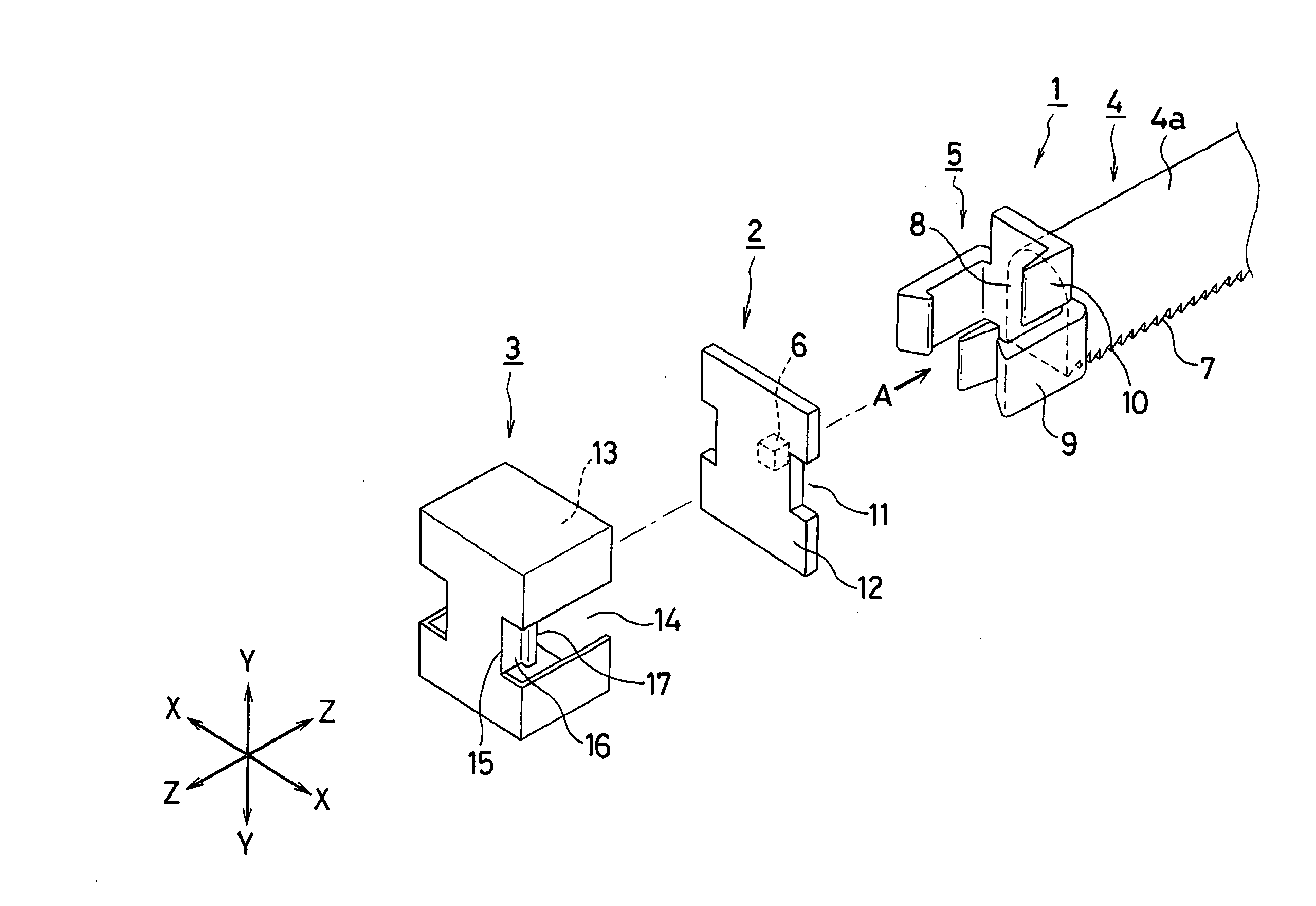
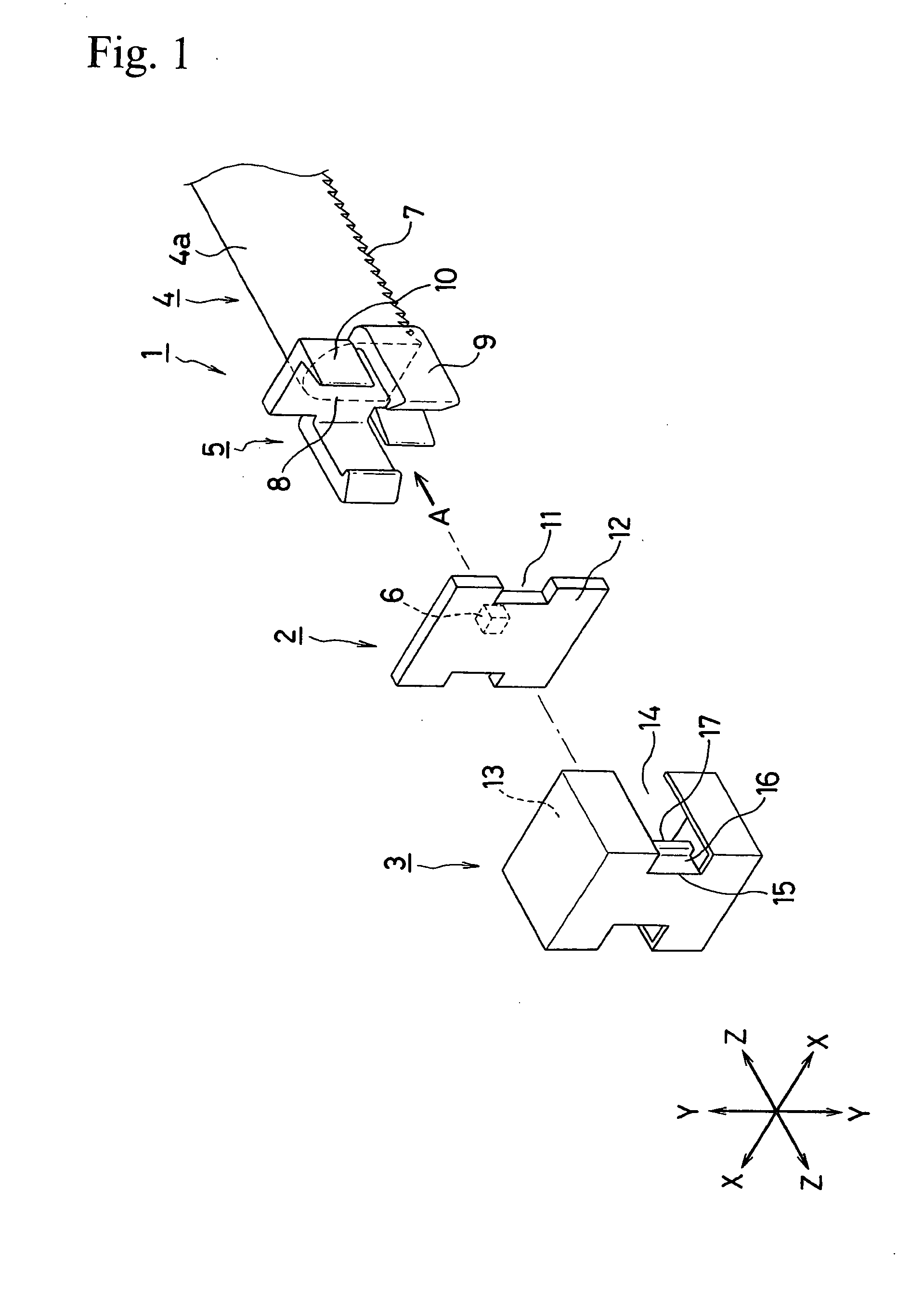
[0032]FIG. 1 is an exploded stereograph showing an embodiment of an illumination device made in accordance with the principles of the invention. This embodiment can include roughly three major components: an optical guide section 1, a light source section 2, and a cover 3.

[0033] The following description is first given with respect to the optical guide section 1. The optical guide section 1 can be composed of a transparent material. Preferably, it is colorless and transparent to suppress loss in light guided through the inside of the guide section 1. The optical guide section 1 can include a light guide 4, which can be sh...


PUM


Abstract

A light access can be integrally formed with a light guide on at least one end of the light guide. A printed circuit board with an LED lamp mounted thereon can be press-fitted in the light access for transient arrangement, and can be fixed by a cover. The position of the printed circuit board can be determined in relation to the light guide. For example, engagement hooks of the light access can be fitted with recesses in the printed circuit board for positioning the circuit board in a plane normal to the longitudinal direction of the light guide. Similarly, positioning ribs of the light guide can be employed for positioning in the longitudinal direction of the light guide. The light guide can be formed in an almost rod shape having four sides in section normal to the longitudinal direction of the light guide. A light guide lens can be formed in one surface and a diffuser cut can be formed in the opposite surface of the light guide.

Description

[0001] This application claims the priority benefit under 35 U.S.C. §119 of Japanese Patent Application No. 2004-133828 filed on Apr. 28, 2004, which is hereby incorporated by reference. BACKGROUND OF THE INVENTION [0002] 1. Field of the Invention [0003] The invention relates to an illumination device or unit for use in vehicular lamps, game machines, decorative illuminations, etc. More particularly, it relates to an illumination device or unit of the type that introduces light into a light guide having a free shape, such as a linear shape, a curved shape, an annular shape, etc., through at least one end of the light guide. [0004] 2. Description of the Related Art [0005]FIG. 6 is an example of the related art showing a method of coupling a light guide 101 to a light source (light emitting diode 102) that emits light that is led to the light guide 101. The light guide 101 is inserted through an open end provided at a guide portion 104 of a body 103 and fixed by a screw 105. A collima...

Claims


Application Information

Patent Timeline
IPC IPC(8): G02B6/00F21S8/10F21V7/04F21V8/00F21V9/00F21V19/00F21Y101/02G02B6/42
CPCF21V5/008F21V19/001F21V19/045G02B6/0038G02B6/0091F21Y2115/10F21S43/19F21S43/14F21S43/237F21S43/247Y10S362/80F21V19/04F21S43/27
Inventor OKAMOTO, HIDEFUMIKONDO, TOSHIYUKIITO, SHINICHI
Owner STANLEY ELECTRIC CO LTD
Why Eureka
Try Eureka