Touch screen input apparatus

a technology of input apparatus and touch screen, which is applied in the direction of instruments, computing, electric digital data processing, etc., can solve the problems of ineffective poor first type of sensor in the presence of external noise, and the electronic apparatus itself and the front surface of the window cannot be effectively blocked, etc., to achieve effective blocking of electrostatic noise, small terminating resistance, and high workability

Inactive Publication Date: 2011-11-17
POINTCHIPS CO LTD
View PDF5 Cites 58 Cited by
  • Summary
  • Abstract
  • Description
  • Claims
  • Application Information

AI Technical Summary

Benefits of technology

[0048]When the present invention, configured and operated as described above, measures the value of capacitance in such a way as to sequentially apply an electrical signal to the first and second electrode patterns which are formed on the first and second electrode layers, respectively, and used to sense capacitance, the present invention applies ground voltage or specific voltage to all the electrodes of each of the electrode patterns other than electrodes which perform sensing, so that there is an advantage of all the areas of the electrodes other than the electrodes which perform sensing being used as electrostatic shield films for protecting the electrodes which sense capacitance from electrostatic noise applied from the outside.
[0049]That is, when the electrode patterns of the first electrode layer perform sensing, some of the electrode patterns of the first electrode layer, which do not perform the sensing, perform a function of shielding electrostatic noise which flows in from the side of sensing electrodes, and the pole-shaped second electrode layer functions as a noise shielding layer in such a way that ground voltage is applied to a sensor sensing area, thereby performing a function of effectively blocking electrostatic noise, abandoned from a display device (Liquid Crystal Device (LCC) or Organic Light Emitting Device (OLED)) placed on the bottom of the second electrodes, in the lower direction. Further, a structure is allowed to perform a function of attenuating noise which flows in from the upper portion due to parasitic capacitance generated because almost the entire area of the first electrode layer which performs sensing is close to that of the second electrode layer to which ground voltage is applied.
[0050]Further, when the electrodes of the second electrode layer perform sensing, some of electrodes of the second electrode layer, which do not perform sensing, block noise components which flow in from a side surface. In the case of noise which flows in from a lower display device or an electronic apparatus itself to the electrode patterns of the second electrode layer, the second electrode patterns have small terminating resistance, that is, about 1 / 10 of the terminating resistance, because of a rectangular pattern structure which is different from the exiting electrode pattern structure (diamond shape), with the result that the terminal intensity of an electrical signal applied to measure capacitance increases and SNR increases 10 times, so that a remarkably small amount of noise flows in, thereby having high workability.
[0051]Further, since about ½ of the area of the electrode patterns of the second electrode layer closely overlap those of the electrode patterns of the first upper layer, the parasitic capacitance, between the capacitance sensing electrode patterns of the first electrode layer and the second electrode layer which function as shield films using ground voltage, also functions to attenuate noise which flows in from the outside.
[0052]Therefore, electrostatic noise which flows in from the outside can be effectively shielded even though a separate ground shield layer is not provided, so that there are advantages of improving the sensitivity of a capacitance touch sensor, reducing the manufacturing cost, improving productivity based on the simplification of work, and increasing the yield of good products when conducting a final examination.
[0053]Therefore, the present invention has excellent advantages of providing a capacitive touch screen input apparatus which may reduce manufacturing cost, being able to shield electrostatic noise, and having excellent linearity and sensitivity, and enabling multiple input.

Problems solved by technology

However, compared with a third type sensor which will be described later, the structure of the first type sensor has a disadvantage in that electrostatic noise, which flows in from the display device 40, the electronic apparatus itself and the front surface of the window, cannot be effectively blocked.
Therefore, since the sensor patterns do not include a ground shield film capable of blocking the inflow of external electrostatic noise, the first type of sensor is very poor in the presence of external noise.
With respect to the application of FIG. 4, generally, when a right triangle-shaped upper electrode group is connected to a single controller control line 27 and a lower electrode group is connected to another single control line 27, there is a problem in that only the difference in human body contact areas generated by a single point (one finger) can be measured in the second axis direction but correct positions cannot be detected in the case of the human bodies of a plurality of users making contact, thereby generating a disadvantage in that multiple user input in a complex form cannot be used.
Meanwhile, when all of the right triangle-shaped upper electrodes and the lower electrodes are separated and then respectively connected to the control lines of the controller, the multiple user input can be sensed but there is a problem in that sensitivity in the second axis direction is remarkably deteriorated.
Further, with regard to the estimation of actual position in the second axis direction, performed using the difference between areas of two facing right triangle-shaped electrodes which are occupied by a human body, it is difficult to measure exact capacitance around the vertex in which the area of a right triangle is very small, that is, around both end points of the right triangles in the second axis direction.
When capacitance is sensed in the vicinity of an end point which is furthest from the part connected to the control line, a value which is much less than actually formed capacitance is sensed, so that there is a problem in that the value of the capacitance generated by actual contact being made with a human body has an asynchronous structure between the part connected to the control line and an end point side.
Further, the concentration distribution of an ITO material which forms a transparent electrode is not constant, with the result that there are many cases where surface resistance (Ω / sgure) is locally non-uniformly distributed, so that it is very difficult to determine the value of a position in the second axis direction of a transparent electrode formed of an ITO material.
Therefore, with regard to an electronic apparatus to which a capacitive touch screen device of that type is applied, there are many cases where a procedure of correcting errors between the value of an actually measured area and the second axis of an actual display device, should be performed at a checking step after completing manufacture and before shipment, so that application is difficult.
Further, there are disadvantages in that sensitivity in one axis direction is excellent but sensitivity in a remaining direction is lowered, in that sensitivity is excellent but resolution for a remaining direction is lowered, in that one more ground layer should be used for a system with much external noise, in that it is disadvantageous for large sized application, in that it is difficult to calculate accurate coordinates because the value of capacitance generated when measurement is performed on both sides of a pattern does not correspond to the coordinates on an actual screen one to one, and in that correction for errors between actually sensed coordinates and a display device requires using a calibration process in the case of production and shipment.
Compared to the first type, this sensor structure has an advantage of effectively blocking electrostatic noise which flows in from the display device 40, the electronic apparatus itself, and the front surface of the window but has a disadvantage of a sensor manufacturing cost or a manufacturing process because a high-priced transparent conductive layer is additionally used.
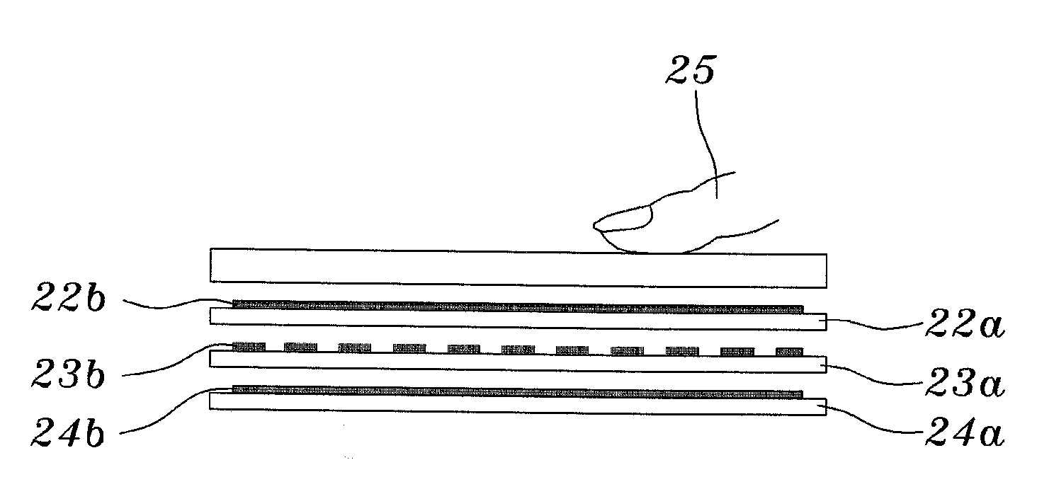
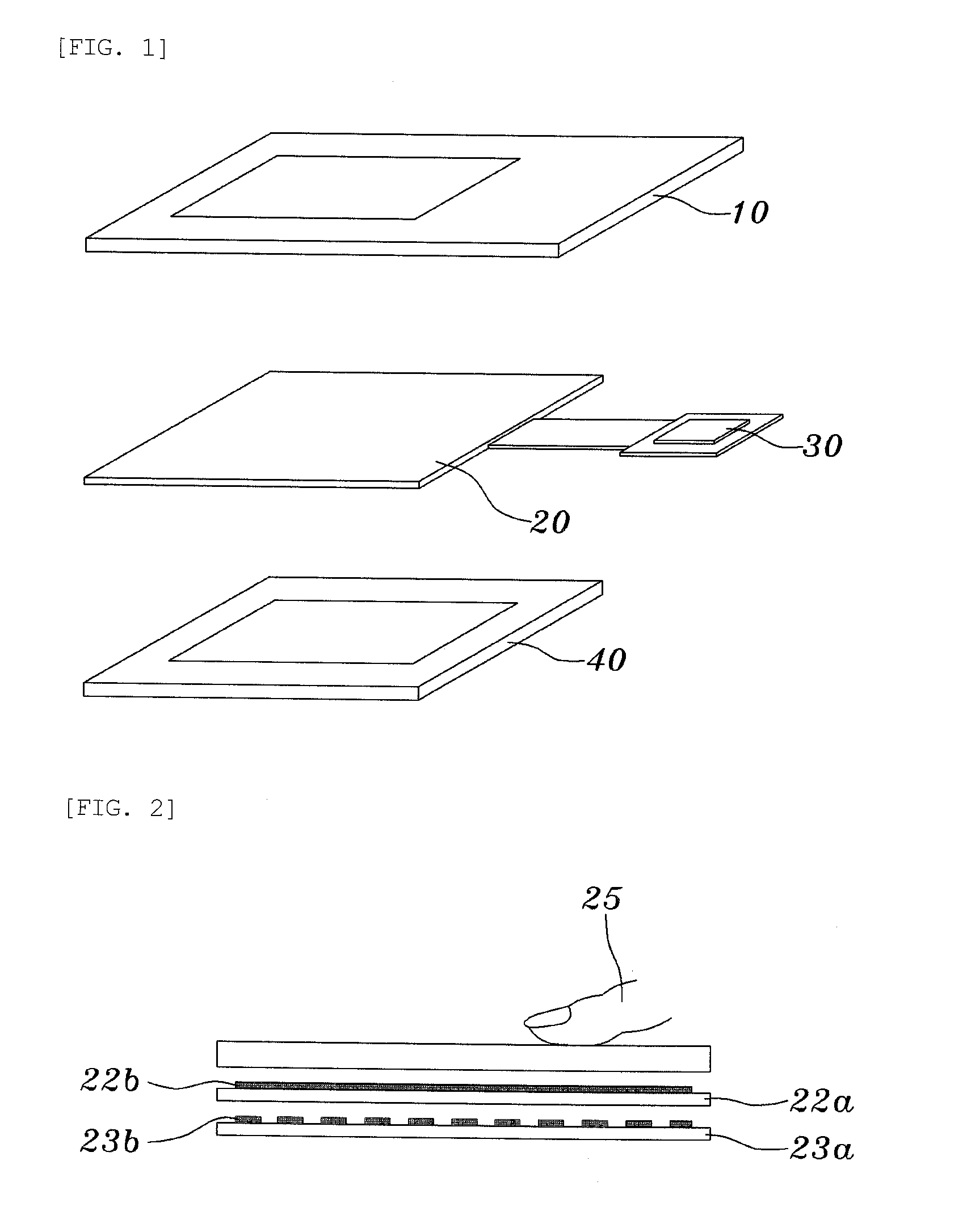
However, the first type does not include a noise shield film layer unlike the three-layered structure, with the result that sensor layers 22b and 23b for detecting capacitance are exposed to the external noise environment as it is, so that there is a disadvantage in that a function of blocking electrostatic noise which flows in from the outside cannot be performed when detecting the change in capacitance generated by contact being made with a human body.
Generally, noise which is generated and flows in from the outside includes the noise of an electronic apparatus system itself which includes a display device close to the bottom of a capacitive sensor, the noise of an inverter stand and an electric motor which flows from the outside of a window (commonly called AC, DC, or R / F noise), and the noise of signal components other than capacitance components that are abandoned from a human body placed in an environment where there is noise.
However, it is difficult to solve the original problem of noise flowing in.
However, unlike the third type, there is not a noise shield film 24b, so that it is difficult to solve the noise problem like the first type and there are the following additional problems.
Although sensitivity and resolution in one direction are good, sensitivity and resolution in another direction are remarkably deteriorated, with the result that it is difficult to determine an accurate position, so that it is difficult to perform cursive script letter recognition and multiple input operation, which are the main functions of a full touch screen.
Further, when the third type of sensor is mounted on finished-product equipment, there is a problem of certainly setting a corrected value for an error between the output coordinates of a capacitive sensor generated by touch and the actual coordinates of a display with respect to an axis direction having low sensitivity whenever shipping the product.
Therefore, it is generally difficult to perform cursive script letter recognition and multiple input operation, which are the main functions of a touch screen.
Further, in the third type, one more layer, that is, a high-priced conductive layer, is used in addition to the first type structure, with the that three layers are finally used, so that a remarkably larger amount of work is required to manufacture a sensor compared to a sensor which uses one or two layers as well as it is expensive to manufacture a sensor, thereby resulting in low productivity.
The manufacturing cost is high due to a configuration having three conductive layers, the brightness of the screen of a display device is deteriorated due to a configuration having three layers, and the overall production yield (ratio of excellent products) decreases due to increased work processes.

Method used


Image

  • Touch screen input apparatus
  • Touch screen input apparatus
  • Touch screen input apparatus

Examples


Embodiment Construction

[0070]Hereinafter, preferred embodiments of a touch screen input apparatus according to the present invention will be described in detail with reference to the attached drawings.

[0071]FIG. 8 is a cross-sectional view illustrating a touch screen input apparatus according to the present invention, FIG. 9 is a plan view illustrating the first electrode layer of the touch screen input apparatus according to the present invention, FIG. 10 is a plan view illustrating the second electrode layer of the touch screen input apparatus according to the present invention, and FIG. 11 is a plan view illustrating a state in which the first and second electrode layers of the touch screen input apparatus according to the present invention have been combined.

[0072]FIG. 12 is a cross-sectional view illustrating a state in which the capacitance of the touch screen input apparatus according to the present invention is measured, FIG. 13 is a view illustrating the state of electrodes when sensing is perfor...


PUM


Abstract

A touch screen input apparatus includes a first electrode layer, a second electrode layer, and a controller. The first electrode layer is configured to perform sensing in a first direction, and provided with first electrode patterns which are formed on the top surface of a substrate. The second electrode layer is configured to perform sensing in a second direction, provided under the first electrode layer, and provided with second electrode patterns which are formed on the top surface of a substrate such that the second electrode patterns overlap the first electrode patterns through a surface on which the first electrode patterns are not formed, and which are spaced apart from each other by predetermined intervals. The control unit is configured to control the electrode patterns other than electrodes which are used to measure capacitance in a ground state.

Description

TECHNICAL FIELD[0001]The present invention relates generally to a touch screen input apparatus, and, more particularly, to a touch screen input apparatus which improves an electrode pattern structure, thereby simultaneously realizing noise and cost reductions.BACKGROUND ART[0002]Generally, a touch screen refers to a screen equipped with a special input device for receiving a corresponding position at the touch of a hand. That is, the touch screen refers to a screen in which, when an object or the hand of a human comes in contact with a letter displayed on the screen or a specific position without using a keyboard, the corresponding position is detected and input data is directly received via the screen such that specific processing may be performed using stored software.[0003]Such a capacitive touch screen includes a window 10 formed of a transparent material, a touch screen (capacitive sensor) 20 configured to sense the touch of a human body, a controller semiconductor (control uni...

Claims


Application Information

Patent Timeline
Patent Type & Authority Applications(United States)
IPC IPC(8): G06F3/045
CPCG02F1/13338G02F2001/133334G06F2203/04107G06F3/044G06F3/0445G06F3/0448G06F3/0446G02F1/133334G06F2203/04103G06F2203/04111G06F3/04182G06F3/0412H10K59/40
Inventor HAN, SANG HYUNKIM, GI BEOM
Owner POINTCHIPS CO LTD
Why Eureka
Try Eureka