Ion funnel with improved ion screening

a funnel and ion technology, applied in the field of funnels, can solve the problems of many ions already lost in front of the skimmer, embodiment of the ion funnel, and many ions lost, and achieve the effects of improving the ion capture, short and effective arrangement, and better transition

Active Publication Date: 2006-06-20
BRUKER DALTONIK GMBH & CO KG
View PDF16 Cites 35 Cited by
  • Summary
  • Abstract
  • Description
  • Claims
  • Application Information

AI Technical Summary

Benefits of technology

[0010]The invention improves the ion funnel by designing the apertured diaphragms of the ion funnel to ensure that the gas escapes easily, the holders for the apertured diaphragms to offer as little resistance as possible to the escaping gas and, at the same time, the holders serve to feed the RF and DC voltages. The invention involves making the ring surface area of at least one third of the apertured diaphragms relatively small, and placing the holders which impede the gas stream relatively far outside the rings. This can be achieved by equipping the rings with moderately long external straps leading to the holders. Although one or two straps per ring may be sufficient, the strap leading to one or two holders, it is also possible to use three straps stretching to three holders. Three straps and three holders impart more mechanical stability to the whole structure of the ion funnel. Furthermore, the invention consists of using the holders as voltage feeders as well. Favorably, the holders are small electric boards to which small extensions of the straps are either snapped or soldered or otherwise fastened. It is advantageous if the boards are positioned with their surface radial to the ion funnel so that they offer little resistance to the gas flow. The boards, in turn, conveniently already contain the ion funnel connections with capacitors and resistors which generate the superposition from the stepped DC voltage and both phases of the RF voltage. This creates a structure which is inexpensive to manufacture.
[0013]The ion funnel is not only useful in the first pump stage; it can also be used in the second pump stage of the differential pumping device. The pressure here is usually in the range 10−2 to 10−1 millibars. The previously used method of capturing these ions with a hexapole or octopole rod system involves a loss of ions because faster ions can overcome the pseudopotential barrier between the rods; the utilization of an ion funnel at this point improves the ion capture and enables a better transition to the next pump stage. Two ion funnels in two differential pump stages provide a short and very effective arrangement. The puller lenses, which, in practice, are preferred for the transfer from one pump chamber to the next can be incorporated into the structure of the ion funnel.

Problems solved by technology

Many ions are already lost in front of the skimmer.
Many ions are lost at this stage, however, because they are entrained outwards in the outflow lobe of the gas and have no chance of reaching the central aperture in the skimmer to the next chamber.
The embodiment of the ion funnel, so far known by publications, is disadvantageous in a number of respects, however.
On the one hand, the diaphragms are held by ceramic posts with spacer rings, and the spacer rings and the necessarily large diaphragm area obstruct the stream of escaping gas; the resistors and capacitors soldered onto the outside edge of the diaphragms represent a further obstruction.
On the other hand, the ion funnel has a relatively large capacitance with relatively large dielectric losses, making it necessary to have a relatively powerful and hence expensive high frequency generator.
Furthermore, the published embodiment has the disadvantage that it only admits a relatively narrow range of the mass-to-charge ratio m / z.

Method used


Image

  • Ion funnel with improved ion screening
  • Ion funnel with improved ion screening
  • Ion funnel with improved ion screening

Examples


Embodiment Construction

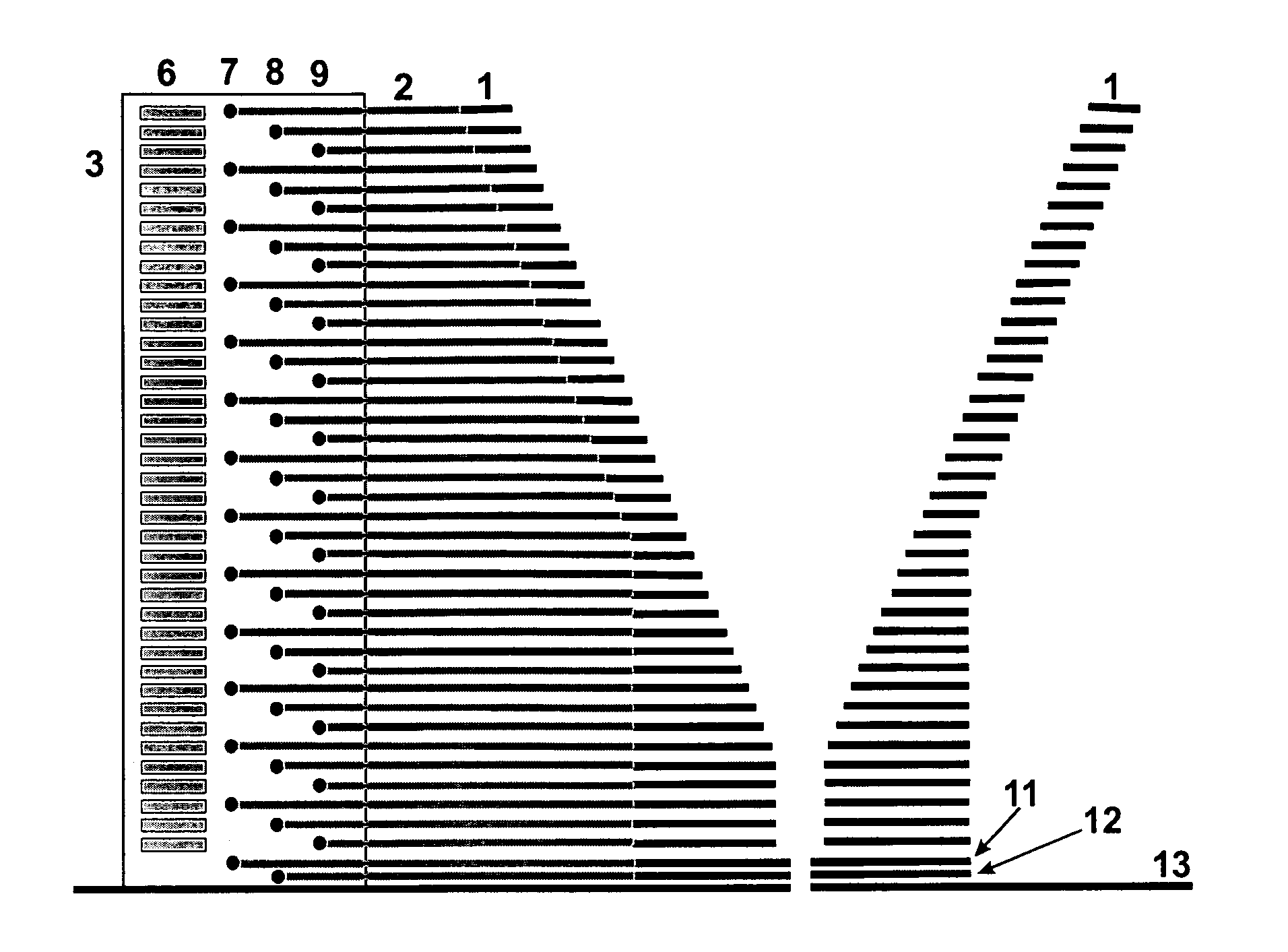
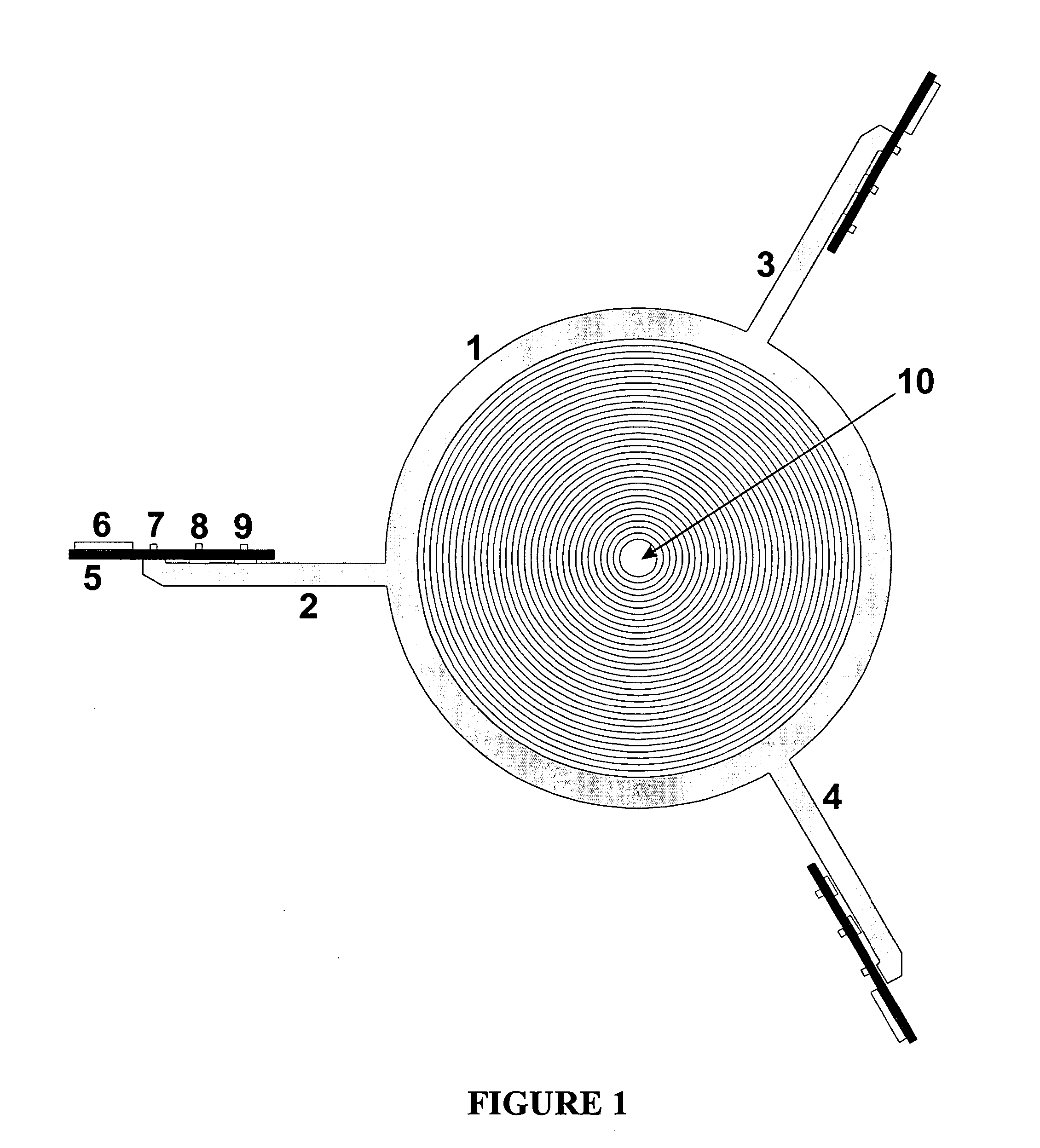
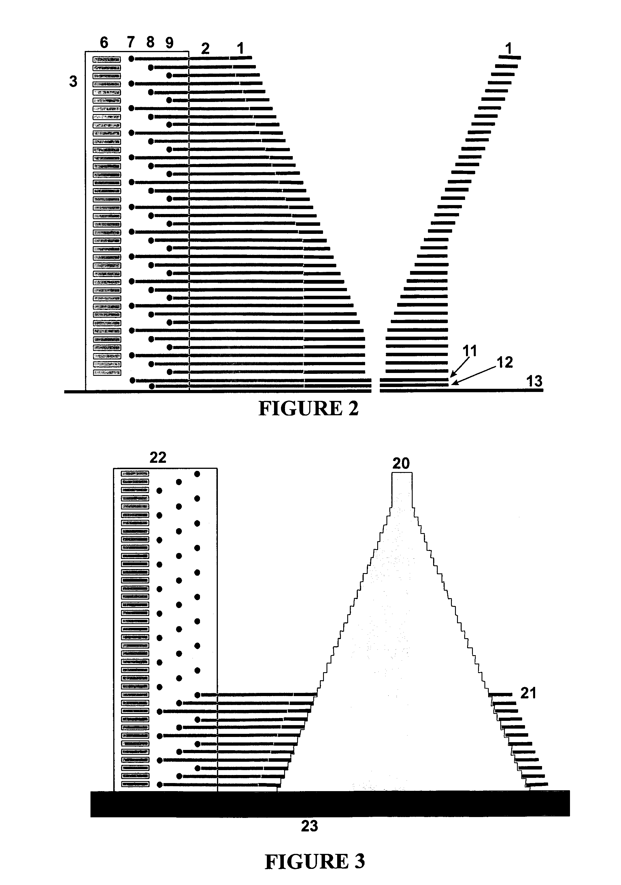
[0018]In modern mass spectrometers, it is becoming more and more common to use ion sources which generate the ions in pure gases at atmospheric pressure. The ions are then usually lead with the pure protective gas through a relatively long capillary (around 160 millimeters long with 500–600 micrometer internal diameter) into the first pump stage of a differential pump unit. Around two to four atmospheric liters of gas per minute are introduced into the vacuum system. Less frequently, simple small apertures of a few hundred micrometers diameter are used instead of the capillaries. Publications and the above cited patent specification describe ion funnels which are used instead of the usual gas skimmer to screen ions from gas streams and to transfer them in a concentrated form. The invention described here relates to an improvement to the ion funnel with respect to high transmission capacity for ions of a wide range of specific masses, easy escape of the gas to achieve a lower pressur...


PUM


Abstract

An ion funnel screen ions from a gas stream flowing into a differential pump stage of a mass spectrometer, transfers them to a subsequent differential pump stage. The ion funnel uses apertured diaphragms between which gas escapes easily. Holders for the apertured diaphragms are also provided that offer little resistance to the escaping gas while, at the same time, serving to feed the RF and DC voltages.

Description

FIELD OF THE INVENTION[0001]The invention relates to a so-called ion funnel whose objective is to screen ions from a gas stream flowing into a differential pump stage of a mass spectrometer and to transfer them to the next differential pump stage.BACKGROUND OF THE INVENTION[0002]In modern mass spectrometers, it is becoming more and more common to use ion sources which generate the ions in pure gases at atmospheric pressure. Electrospray ion sources are one example, but other types, such as atmospheric pressure MALDI (ionization by matrix-assisted laser desorption) have also become commercially available in the meantime. In these types of mass spectrometer with out-of-vacuum ion generation, the ions must initially be introduced into the vacuum system through apertures or capillaries together with a lot of gas; they must then be separated as far as possible from the gas and transported through various differential pump stages to the actual mass separating system, the mass spectrometri...

Claims


Application Information

Patent Timeline
Patent Type & Authority Patents(United States)
IPC IPC(8): H01J37/301H01J49/24H01J49/00H01J49/06H01J49/42
CPCH01J49/066H01J49/06
Inventor FRANZEN, JOCHEN
Owner BRUKER DALTONIK GMBH & CO KG
Why Eureka
Try Eureka