Valve arrangement for reciprocating machinery such as a pump and an compressor

a reciprocating machinery and valve body technology, applied in machines/engines, positive displacement liquid engines, liquid fuel engines, etc., can solve the problems of time-consuming and laborious replacement of valve components, and affecting the work efficiency of the machine. , to achieve the effect of simplifying the work

Active Publication Date: 2007-11-20
GRANT PRIDECO LP
View PDF10 Cites 58 Cited by
  • Summary
  • Abstract
  • Description
  • Claims
  • Application Information

AI Technical Summary

Benefits of technology

[0005]It is an object of the invention to provide a valve arrangement for reciprocating machinery, where the flow forces cause little or no misalignment of the valve body. It is a further object to simplify the work involved in changing valves.

Problems solved by technology

Such a change in direction results in lateral flow forces that act on the valve body and cause misalignment of this.
The result is skewed or uneven wear on the valve body and the valve seat, which causes leakage in a closed valve.
Changing valves or worn valve components may be time consuming, particularly in the case of large reciprocating machinery such as a reciprocating pump for drill fluid for use in drilling of petroleum wells.

Method used


Image

  • Valve arrangement for reciprocating machinery such as a pump and an compressor
  • Valve arrangement for reciprocating machinery such as a pump and an compressor
  • Valve arrangement for reciprocating machinery such as a pump and an compressor

Examples


Embodiment Construction

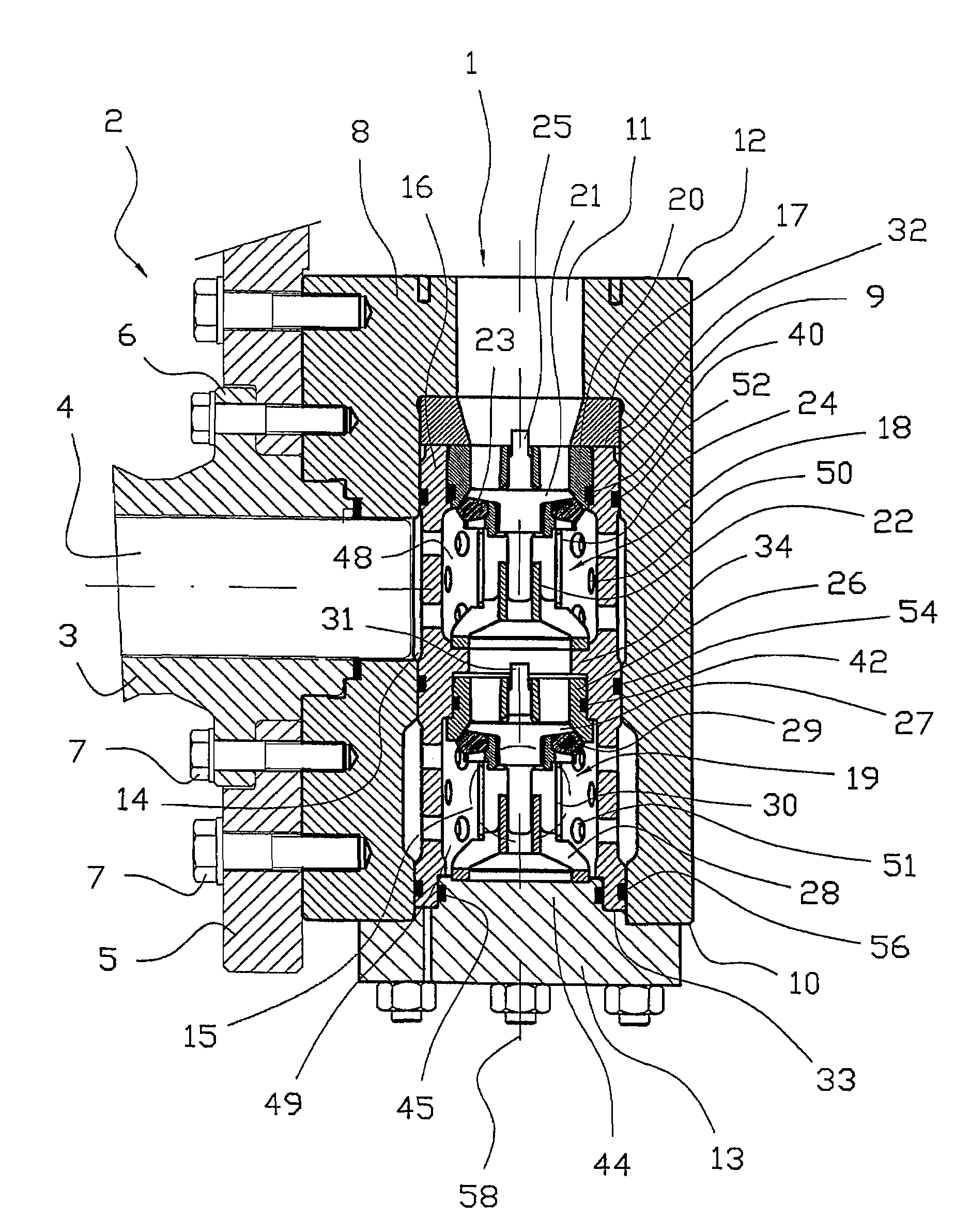
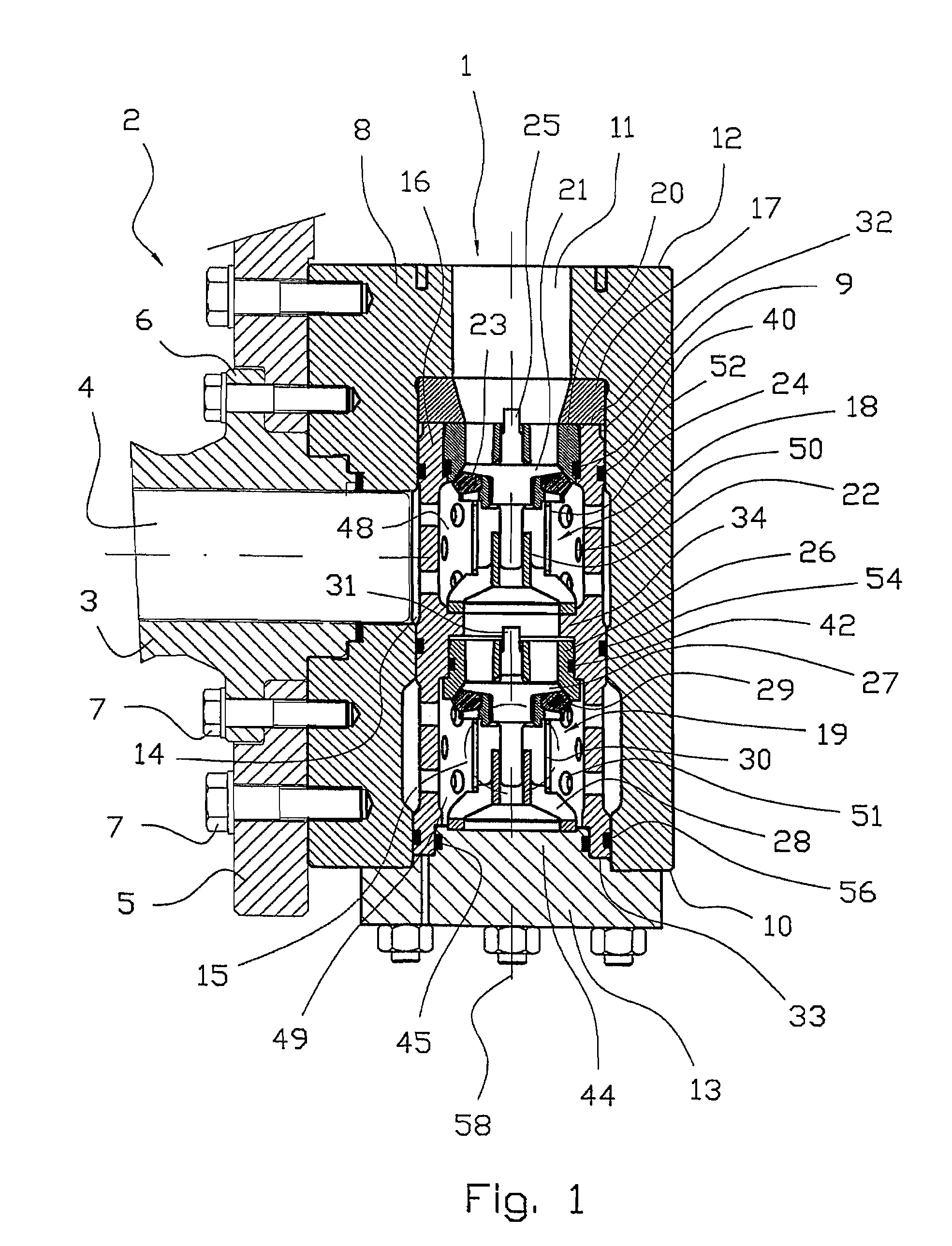
[0026]In FIG. 1, reference number 1 denotes a valve arrangement mounted on a piston pump 2 and connected to the cylinder 3 of this, in which a reciprocating piston 4 is arranged in a known manner. An assembly plate 5 forms an extension of a flange 6 on the cylinder 3. The assembly plate 5 and the valve arrangement 1 are attached to the flange 6 and thereby to the cylinder 3 by the use of screws 7.

[0027]The valve arrangement 1 comprises a casing 8 in which a bore 9 that is open at one end 10 of the casing 8 ends within the casing 8 and joins an inlet 11 that is open at the other and opposite end of the casing 8. A cover 13 is designed to cover the bore 9 at the first end 10 of the casing 8.

[0028]A working passage 14 in the casing 8 forms an extension of the cylinder 3, to allow it to communicate with the bore 9. An outlet 15 leading from the bore and out of the casing 8 is shown in broken lines in FIG. 1. The inlet 11 and the outlet 15 are designed to be connected to piping systems (...


PUM


Abstract

A valve arrangement for reciprocating machine, where the arrangement (1) comprises an in-valve (18) and an out-valve (19), each valve (18), (19) being a springloaded one-way valve designed to open for flow when the pressure differential in the direction of flow provides a force that exceeds the spring tension, wherein the valves (18, 19) are mounted in a casing (8) that forms or is connected to the cylinder head of the reciprocating engine (2). The in-valve (18) and the out-valve (19) are mounted in a sleeve (16) designed to be fitted in a bore (9) in the casing (8), and where fluid may flow to the sleeve (16) from an inlet (11) in the casing (8) and into the sleeve (16) via the in-valve (18), and where the sleeve (16) is provided with at least one perforated area where fluid may flow radially out of or into the sleeve (16) via holes (50, 51), thereby flowing to or from a passage (14, 15) that forms a perpendicular or near perpendicular connection with the bore (9).

Description

CROSS REFERENCE TO RELATED APPLICATION[0001]The present application is the U.S. national stage application of International Application PCT / NO03 / 00092, filed Mar. 18, 2003, which international application was published on Oct. 2, 2003 as International Publication WO 03 / 081047. The International Application claims priority of Norwegian Patent Application 20021434, filed Mar. 21, 2002.BACKGROUND OF THE INVENTION[0002]The invention regards a valve arrangement for reciprocating machinery such as a pump and a compressor.[0003]Reciprocating machinery, or a reciprocating engine, typically has an induction valve and an exhaust valve, hereinafter termed in-valve and out-valve, for each piston. Normally, springloaded one-way valves are used, where a spring closes the valve by forcing a valve body against a valve seat. A valve may be opened for flow either through mechanical action or by pressure in the working medium of the reciprocating engine, hereinafter termed fluid, acting on the valve b...

Claims


Application Information

Patent Timeline
Patent Type & Authority Patents(United States)
IPC IPC(8): F16K11/07F04B53/10F16K15/06
CPCF16K15/066F04B53/109Y10T137/7838Y10T137/7559
Inventor MOE, MAGNEKYLLINGSTAD, .ANG.GE
Owner GRANT PRIDECO LP
Why Eureka
Try Eureka