Radio receiver and gain control method

a gain control and receiver technology, applied in the field of radio receivers, can solve the problems of deteriorating s/n ratio of input signals, signal distortion or clipping, and inability to perform appropriate agc control

Inactive Publication Date: 2006-04-13
FUJITSU LTD
View PDF2 Cites 22 Cited by
  • Summary
  • Abstract
  • Description
  • Claims
  • Application Information

AI Technical Summary

Benefits of technology

[0008] It is an object of the present invention to at least solve the above problems in the conventional technology.
[0009] A radio receiver according to one aspect of the present invention includes a receiving unit configured to receive a radio signal in which a first signal and a second signal are time-multiplexed in a frame; and a gain-control unit configured to perform a gain control on the radio signal with a different gain for each of the first signal and the second signal.
[0010] An gain control method according to another aspect of the present invention includes receiving a radio signal in which a first signal and a second signal are time-multiplexed in a frame; and performing a gain control on the radio signal with a different gain for each of the first signal and the second signal.

Problems solved by technology

Therefore, when a power difference occurs between time slots within the monitored cycle, appropriate AGC control cannot be performed.
Hence, the input level with respect to analog devices such as an amplifier and a mixer, and the ADC in the subsequent stage is not appropriate, thereby causing a problem in that an S / N ratio of the input signal deteriorates, or on the contrary, signal distortion or clipping occurs.
Accordingly, the unit price of the necessary device increases, thereby increasing the whole price of the radio receiver.

Method used


Image

  • Radio receiver and gain control method
  • Radio receiver and gain control method
  • Radio receiver and gain control method

Examples


first embodiment

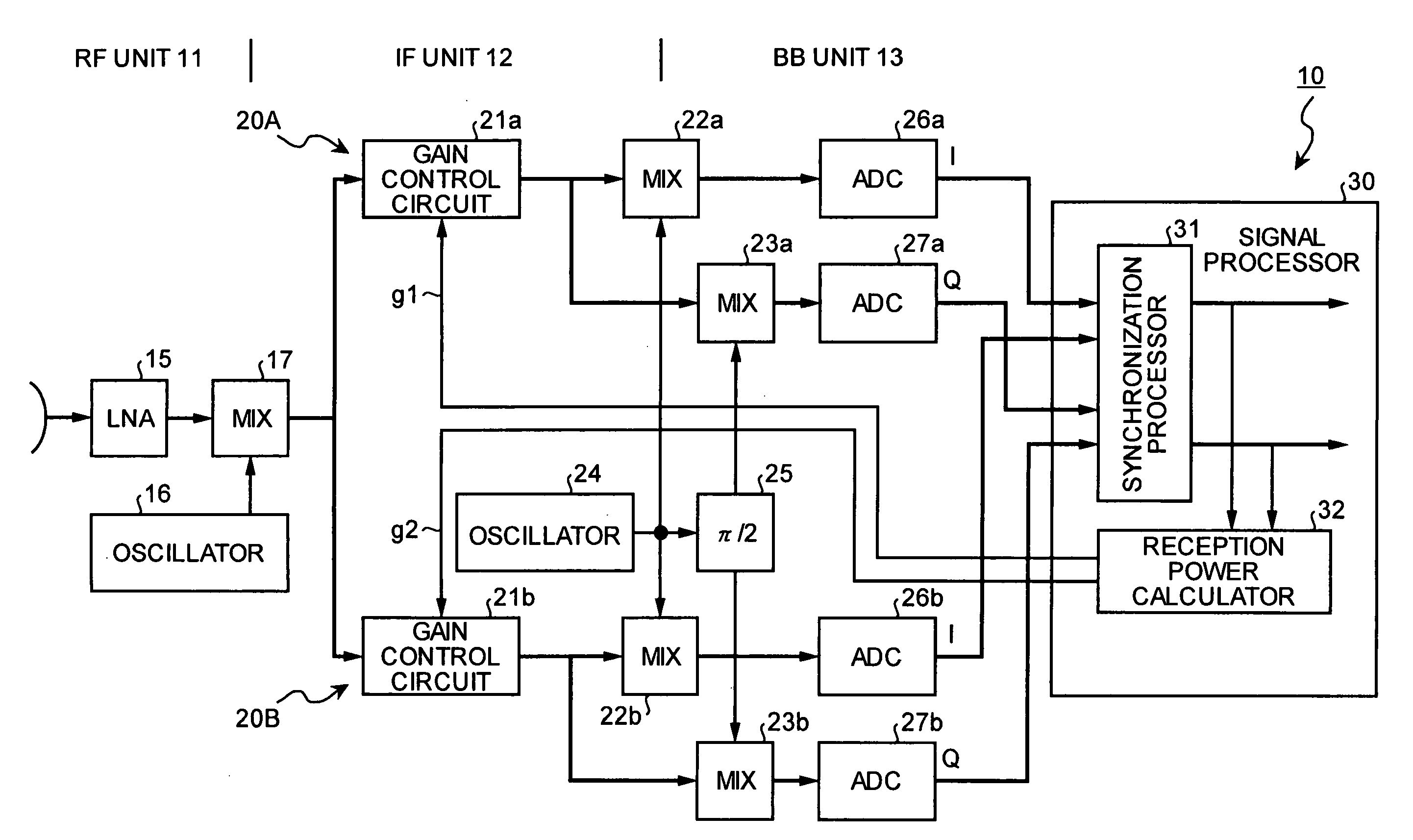
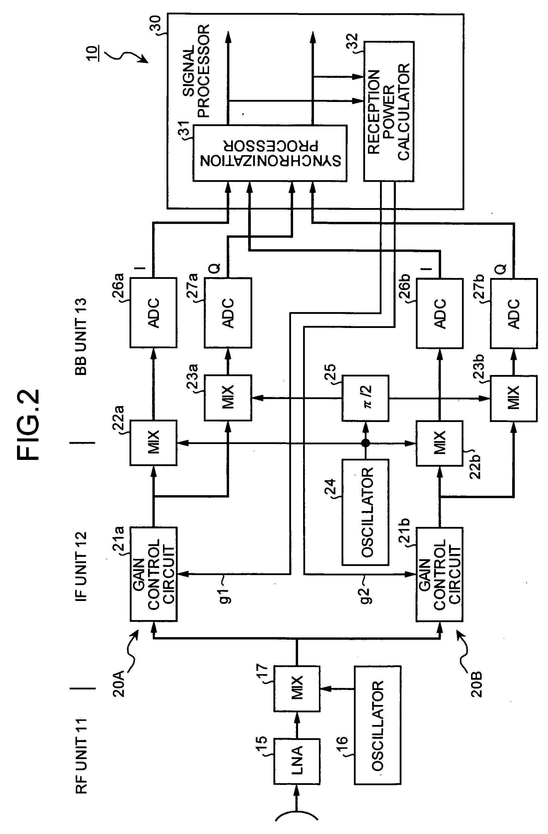
[0029]FIG. 2 is a block diagram of a radio receiver according to the present invention. As the radio receiver is, for example, a mobile station in a mobile communication system. A radio receiver 10 includes an RF unit 11 that handles high frequency band signals, an IF unit 12 that handles medium frequency band signals, and a BB unit 13 that handles base-band signals. In the RF unit 11, high frequency band input signals go through a low noise amplifier (LNA) 15, and are mixed with a signal from an oscillator 16 by a mixer (MIX) 17, thereby being converted to IF frequency band signals.

[0030] The signal input to the IF unit 12 is branched into two to be input to gain control circuits 21 (21a and 21b) of the respective systems. The signal is by simply branched into two while maintaining the frame configuration. One of the branched systems is a gain control system 20A for the common pilot signal 2 and the other is a gain control system 20B for the individual data signal 3. These gain con...

second embodiment

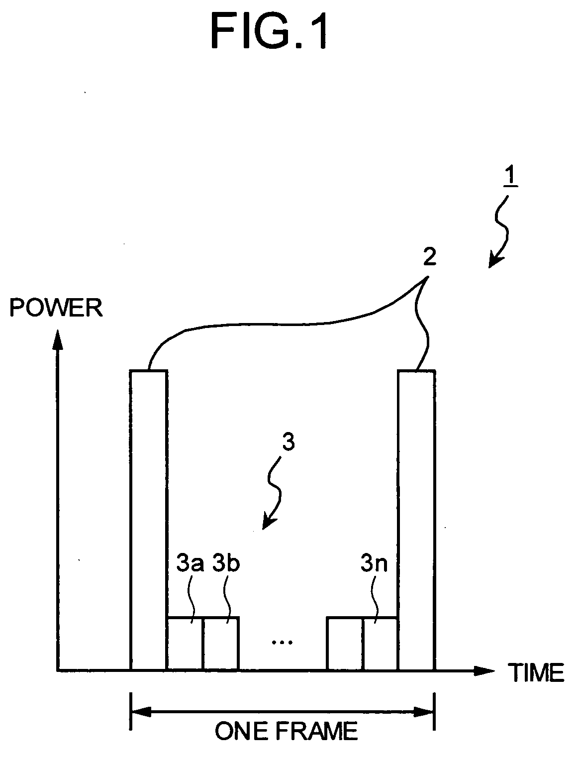
[0060] when a frame is received, in which the common pilot signal and data signals of one or a plurality of users are arranged in a time-sharing manner in a unit of time slot, appropriate gain control is performed respectively for each time slot having received these common pilot signals and data signals. Accordingly, even if there is a difference in the power of the common pilot signal and the data signal in each time slot, the common pilot signal and the data signal can be received, with a wide dynamic range being ensured, thereby preventing signal deterioration and improving the reception quality.

[0061] The received frame format in the first and the second embodiments is not limited to the frame configuration described above (see FIG. 1), and can be applied to other frame formats.

[0062]FIG. 9 depicts another frame format of the radio signal to be received by the radio receiver according to embodiments of the present invention. Time is plotted on the horizontal axis and power is...


PUM


Abstract

A radio receiver includes a branching unit, a first gain-control system, a second-gain control system, and a signal processing unit. The branching unit branches a radio signal received by the radio receiver into two signals. The first-gain control system performs a gain control of a pilot signal in one of branched signals, and the second gain control system performs a gain control of a data signal in another of the branched signals. The signal processing unit synchronizes frames in the received radio signal. The signal processing unit outputs a gain signal to each of the first gain-control system and the second gain-control system. The first gain-control system and the second gain-control system perform the gain controls based on the gain signal.

Description

BACKGROUND OF THE INVENTION [0001] 1. Field of the Invention [0002] The present invention relates to a radio receiver that receives a radio signal and performs an automatic gain control on the radio signal. [0003] 2. Description of the Related Art [0004] A general radio receiver includes an automatic gain control (AGC) function for adjusting a gain corresponding to an electric power (or a voltage) of an input signal. The AGC function increases a gain of an amplifier when an input power is smaller than a predetermined reference power (or decreases an attenuation by a variable attenuator), or decreases the gain of the amplifier when the input power is larger than the reference power, or increases the attenuation by the variable attenuator. Accordingly, the level of the received signal is kept constant to be input to an analog-digital converter (ADC), thereby realizing a wide dynamic range. [0005] The reference power in such an AGC circuit is fixed at a constant value. Furthermore, it ...

Claims


Application Information

Patent Timeline
Patent Type & Authority Applications(United States)
IPC IPC(8): H04B17/02H04B1/06H04B17/40H03G3/00H03G3/20H03G3/30H04B1/16H04B7/005H04J3/00H04J11/00
CPCH03G3/005H03G3/3052H03G3/3078H03G3/3089H03G2201/103H03G2201/202H03G2201/305H04B1/707H04B2201/70701H04B2201/70706
Inventor SATO, TADAHIROADACHI, AKIFUMI
Owner FUJITSU LTD
Why Eureka
Try Eureka