Safety Monitoring and Locating System

a safety monitoring and locating system technology, applied in the field of safety, can solve the problems of crewmembers of large ships working in dangerous conditions, confined spaces, and crew members on ships at sea always at risk of falling overboard and becoming lost at sea

Inactive Publication Date: 2007-10-04
BRIAR TEK IP
View PDF4 Cites 23 Cited by
  • Summary
  • Abstract
  • Description
  • Claims
  • Application Information

AI Technical Summary

Benefits of technology

[0007]The user unit can also include a sensor interface that is adapted to receive an output signal from a sensor device, and a user unit processor that is adapted to format the sensor device output signal for transmission by the radio beacon as a component of the radio signal. The base station processor can also be adapted to format the received radio signal for display on the output device such that the content of the sensor device output signal is displayed. The sensor interface can be adapted to receive the output signal from any of a number of different types of sensor devices. The user unit can also include a sensor device that is coupled to the sensor interface. The se

Problems solved by technology

Crew members of large ships often work in dangerous, confined spaces.
They also often work alone or in areas where it is not practical to provide a safety watch.
Due to the unique structure of

Method used


Image

  • Safety Monitoring and Locating System
  • Safety Monitoring and Locating System
  • Safety Monitoring and Locating System

Examples


Embodiment Construction

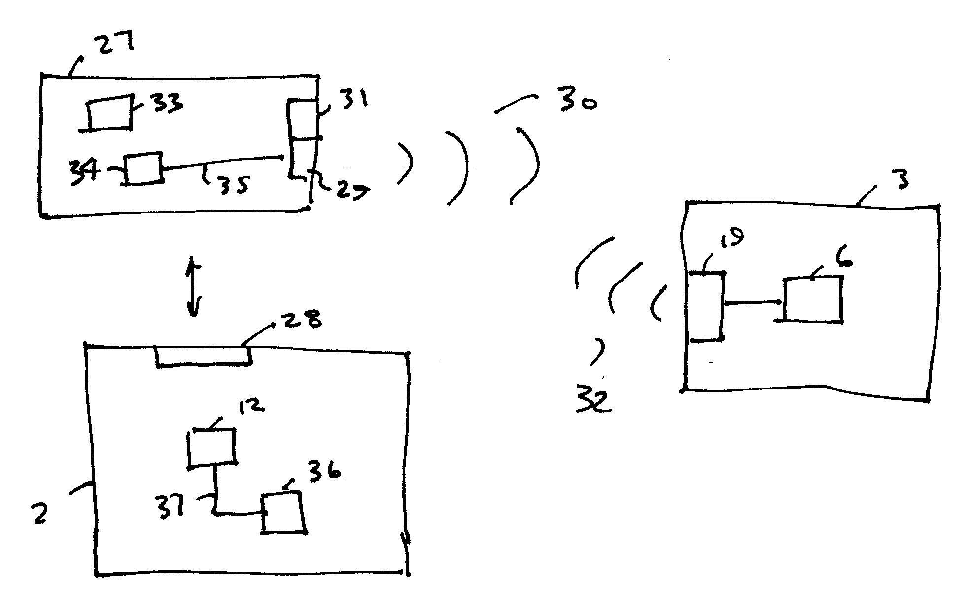
[0026]Various embodiments of the apparatus of the invention include individual beacon devices worn by crew members, tag readers (either active or passive), signal repeaters, and a base station. Each individual in the system wears a beacon device, which consists of a radio beacon, a wireless data network node, and a sensor interface that can indicate alarm conditions. Examples of alarm conditions include submersion in water, lack of motion, abnormal temperature, or abnormal pulse rate. Other sensors or biometrics can also be used. Each beacon can communicate with other beacons in a mesh network and as needed signal repeaters can be placed throughout the ship to ensure complete system coverage. Preferably, multiple modes of communication are available for use with the system, to provide flexibility and reliability in dealing with a challenging communication environment.

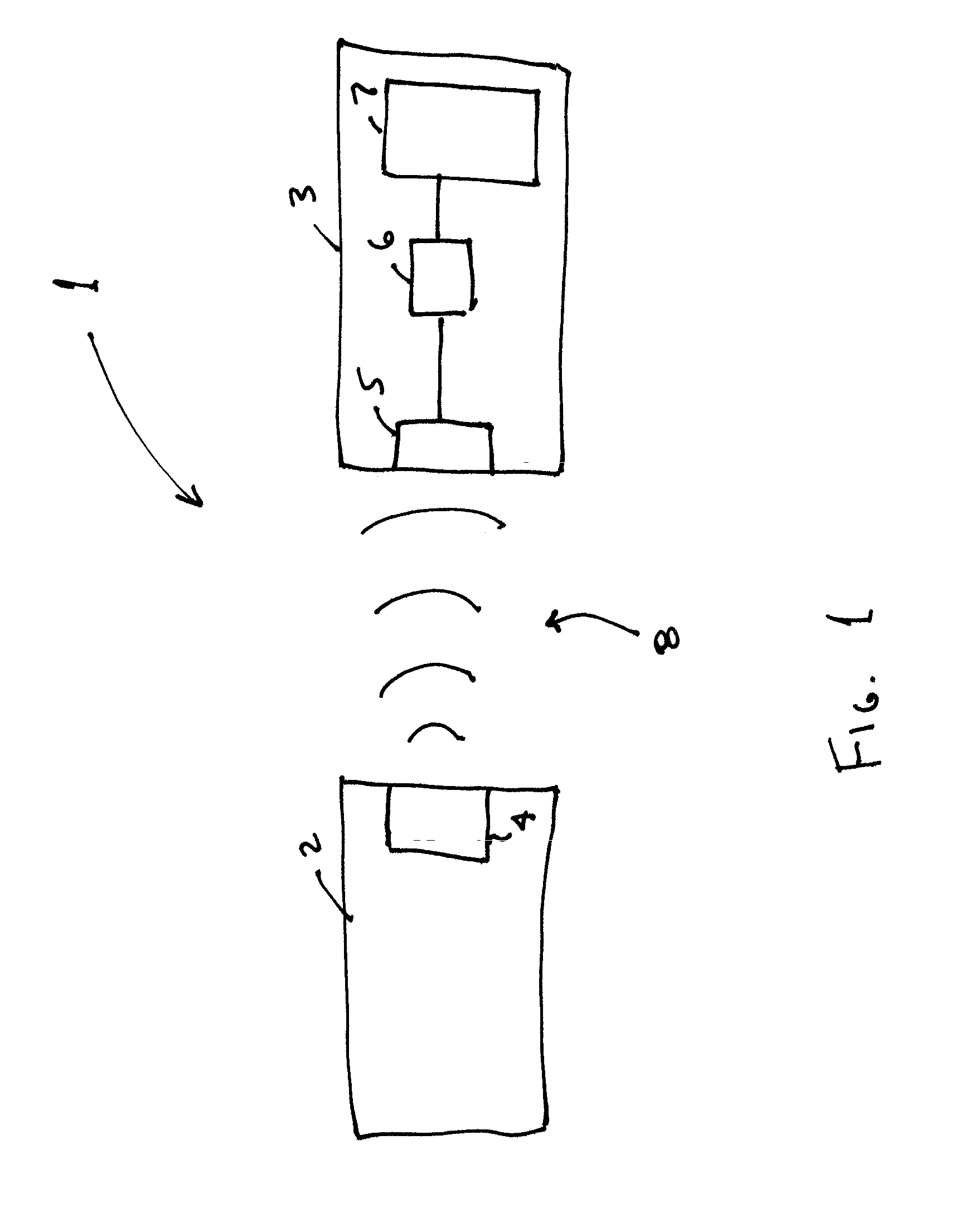
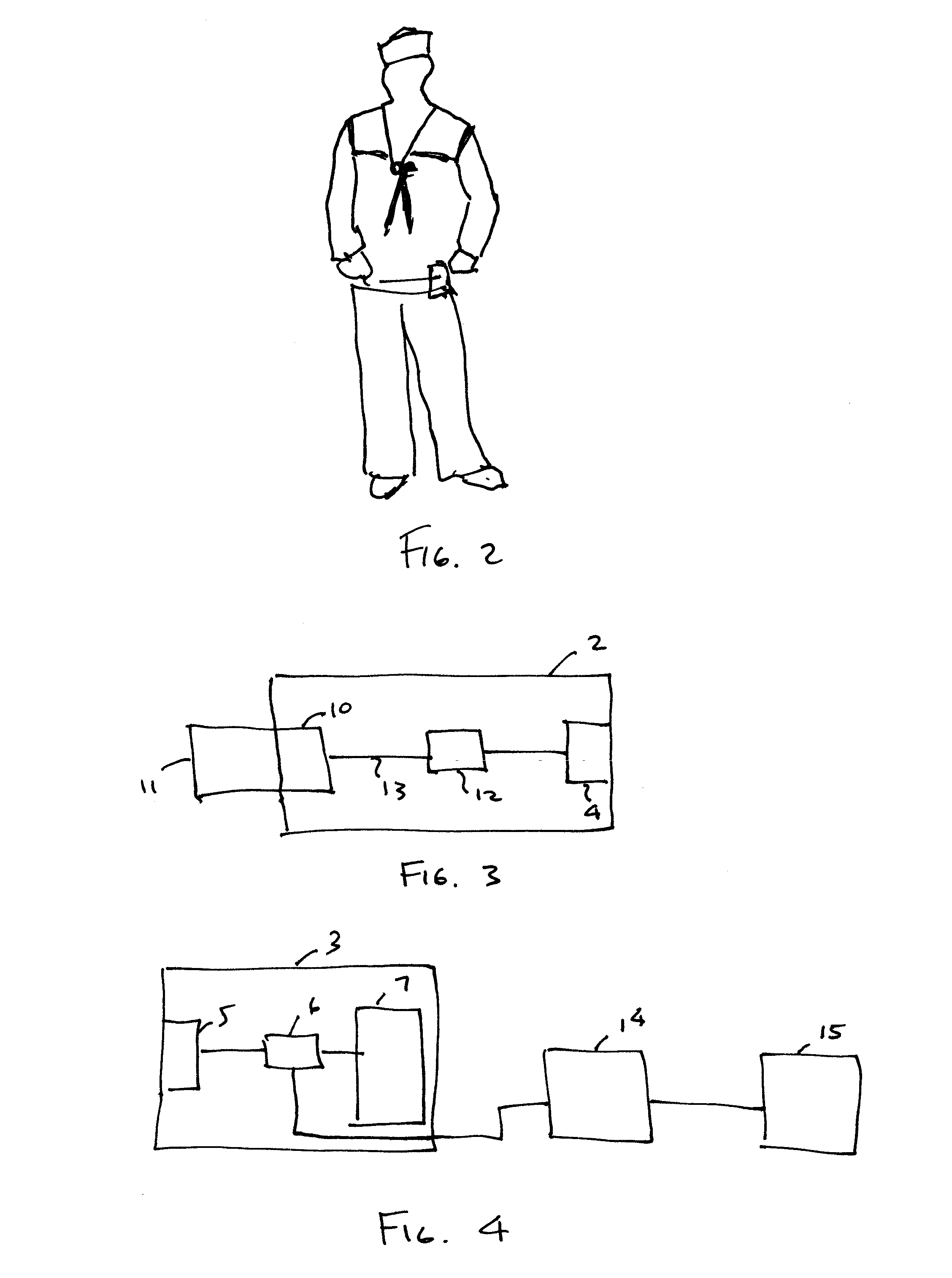
[0027]As shown in FIG. 1, a monitoring system 1 includes a user unit 2 and a base station 3. The user unit 2 is inten...


PUM


Abstract

A monitoring system includes a user unit and a base station. The user unit includes a radio beacon that transmits a radio signal identifying a particular user. The base station includes a radio receiver that receives the radio signal, a processor that formats the received radio signal for display on an output device, and an output device that displays an indication of reception of the radio signal and an indication of the identity of the user. The user unit can also include a sensor interface that receives an output signal from a sensor device, and a processor that formats the sensor device output signal for transmission by the radio beacon as a component of the radio signal. The base station processor can also format the received radio signal for display on the output device such that the content of the sensor device output signal is displayed.

Description

CROSS-REFERENCE TO RELATED APPLICATION[0001]This is related to, and claims the benefit under 35 USC §119(e) of U.S. Provisional Application for Patent No. 60 / 786,828, which was filed on Mar. 28, 2006.FIELD OF THE INVENTION[0002]The invention relates to safety and in particular to the monitoring of the wellbeing and location of personnel working inside large structures, or in any other isolated or enclosed environment. For example, the invention has particular application to maritime safety in monitoring the wellbeing and location of crew on board a ship.BACKGROUND OF THE INVENTION[0003]Crew members of large ships often work in dangerous, confined spaces. They also often work alone or in areas where it is not practical to provide a safety watch. Due to the unique structure of most ships, conventional radios or other safety communications are not appropriate. Additionally, crewmembers on ships at sea are always at risk of falling overboard and becoming lost at sea. A need exists to mo...

Claims


Application Information

Patent Timeline
IPC IPC(8): G08B1/08G08B13/14G08B23/00
CPCG08B21/02
Inventor COLLINS, CHARLES K.LANDA, JOSEPH
Owner BRIAR TEK IP
Why Eureka
Try Eureka