One-piece fiber optic receptacle having chamfer and alignment ribs

a fiber optic receptacle and one-piece technology, applied in the field of fiber optic receptacles, can solve the problems of reducing the float between the plug ferrule and the alignment sleeve, affecting the quality of the molded surface of the external two-piece design, and requiring strict control and maintenance of the high-quality molded surface. , to achieve the effect of improving the support of the alignment sleeve and the biasing member, and facilitating

Active Publication Date: 2006-04-27
CORNING CABLE SYST LLC +1
View PDF14 Cites 80 Cited by
  • Summary
  • Abstract
  • Description
  • Claims
  • Application Information

AI Technical Summary

Benefits of technology

[0008] To achieve the foregoing and other objects, and in accordance with the purposes of the invention as embodied and broadly described herein, the present invention provides various embodiments of a fiber optic receptacle assembly, and more particularly, a fiber optic receptacle having an improved alignment sleeve retainer and biasing member supports. Thus, the present invention provides a fiber optic receptacle designed to readily align and mate any like pair of opposed optical connectors or ferrules in a precise and secure manner, while providing strain relief against pulling forces of up to about 600 lb / ft.

Problems solved by technology

While the latches effectively secure the plug ferrule within the alignment sleeve, mechanical coupling disadvantageously limits float between the plug ferrule and the alignment sleeve.
In testing these receptacle designs, it has been determined that the biasing springs are subject to deformation during loading and ferrule insertion.
In addition, an external two-piece design requires strict control and maintenance of high-quality molded surfaces.

Method used


Image

  • One-piece fiber optic receptacle having chamfer and alignment ribs
  • One-piece fiber optic receptacle having chamfer and alignment ribs
  • One-piece fiber optic receptacle having chamfer and alignment ribs

Examples


Embodiment Construction

[0021] The present invention will now be described more fully hereinafter with reference to the accompanying drawings in which exemplary embodiments of the invention are shown. However, this invention may be embodied in many different forms and should not be construed as limited to the embodiments set forth herein. These exemplary embodiments are provided so that this disclosure will be both thorough and complete, and will fully convey the scope of the invention to those skilled in the art. Like reference numbers refer to like elements throughout the various drawings.

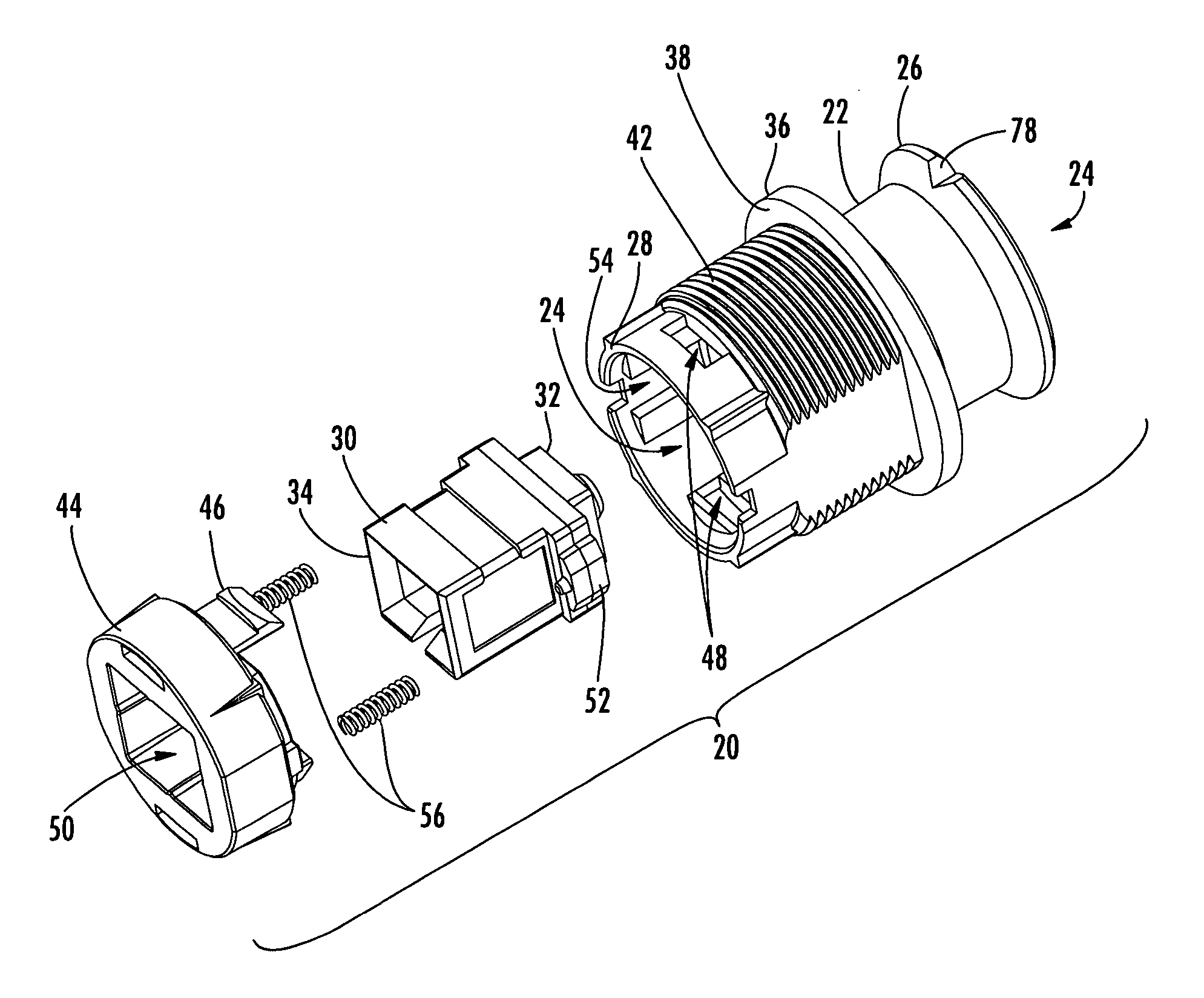
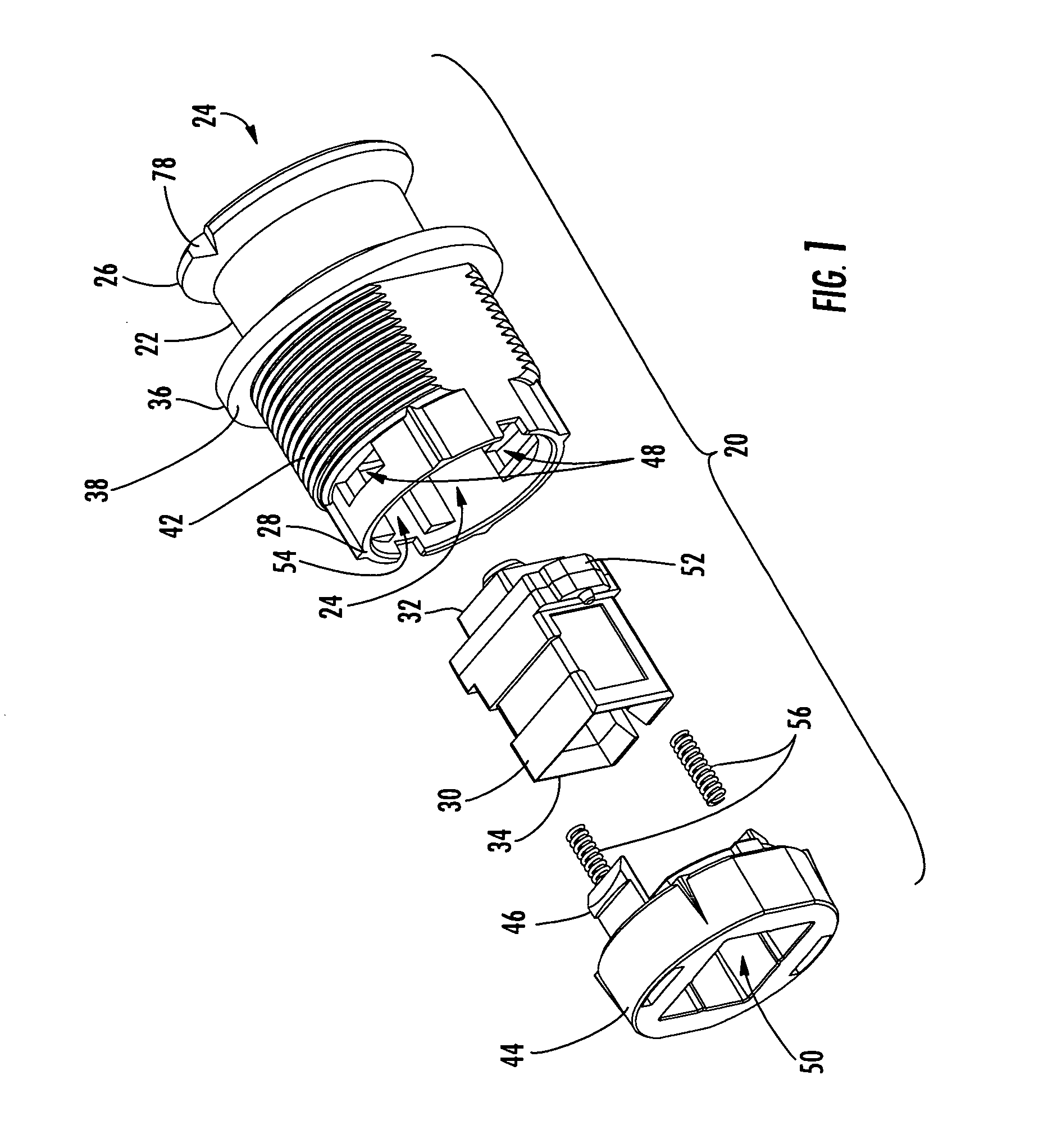
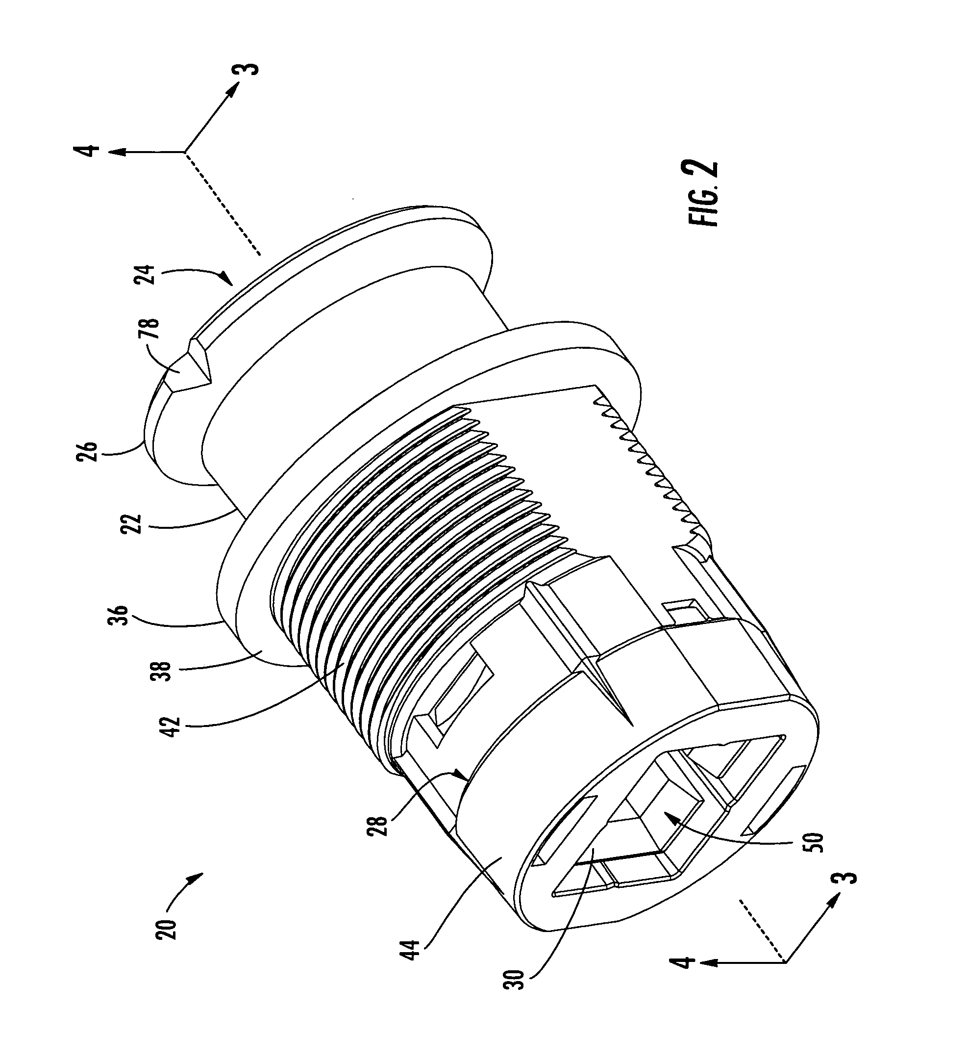
[0022] The various embodiments described below provide a fiber optic receptacle having an external one-piece design that eliminates the need for an internal seal, while permitting access to an alignment sleeve from only the back-side of the receptacle. The external one-piece design is an improvement over conventional external two-piece designs that permits the receptacle assembly to pass freeze / thaw cycle testing and p...


PUM


Abstract

A one-piece fiber optic receptacle is provided for aligning and optically connecting a plug ferrule with a back-side ferrule of like configuration. The fiber optic receptacle includes a receptacle housing defining an internal cavity opening through an external end and an opposed internal end, an alignment sleeve disposed within the internal cavity and received within the internal end of the receptacle housing, and a sleeve retainer secured to the internal end of the receptacle housing and operable for providing access to the alignment sleeve from the internal end of the receptacle housing. The alignment sleeve includes a chamfer for guiding the back-side ferrule into the alignment sleeve. The sleeve retainer has an opening and a plurality of alignment ribs disposed about the opening for permitting angular rotation of the alignment sleeve relative to the sleeve retainer during insertion of the plug ferrule and the back-side ferrule into the alignment sleeve.

Description

BACKGROUND OF THE INVENTION [0001] 1. Field of the Invention [0002] The present invention relates generally to a fiber optic receptacle for interconnecting optical fibers within a communications network, and more specifically, to a fiber optic receptacle that provides improvements in freeze / thaw cycle performance, sealing and connector alignment. [0003] 2. Description of the Related Art [0004] Fiber optic networks are currently revolutionizing the telecommunications industry due to their high bandwidth carrying capacity, low signal degradation and low power usage. As a result, fiber optic networks are being created and expanded to deliver “fiber-to-the-curb” (FTTC), “fiber-to-the-business” (FTTB), “fiber-to-the-home” (FTTH), “fiber-to-the-premises” (FTTP) and “fiber-to-the-subscriber” (FTTS), referred to generically as “FTTx.” In order to provide services to one of these subscriber locations, fiber optic networks must include a large number of interconnection points in which optical...

Claims


Application Information

Patent Timeline
Patent Type & Authority Applications(United States)
IPC IPC(8): G02B6/38
CPCG02B6/3874
Inventor TRAN, HIEU V.LIU, XINLUTHER, JAMES P.THEUERKORN, THOMASYOW, CHARLES A. JR.
Owner CORNING CABLE SYST LLC
Why Eureka
Try Eureka