Audio receiver having adaptive buffer delay

Inactive Publication Date: 2006-05-04
PIVOT VOIP
View PDF6 Cites 35 Cited by
  • Summary
  • Abstract
  • Description
  • Claims
  • Application Information

AI Technical Summary

Benefits of technology

[0024] However, the present inventor has found inefficiencies with each of the existing adaptive jitter buffers. Accordingly, the present invention is directed to an improvement over conventional adaptive jitter buffers. Generally speaking, the present invention provides a systematic technique for increasing and decreasing jitter buffer delay by utilizing various combinations of: evaluating received data ov

Problems solved by technology

However, the present inventor has found inefficienci

Method used


Image

  • Audio receiver having adaptive buffer delay
  • Audio receiver having adaptive buffer delay
  • Audio receiver having adaptive buffer delay

Examples


Example

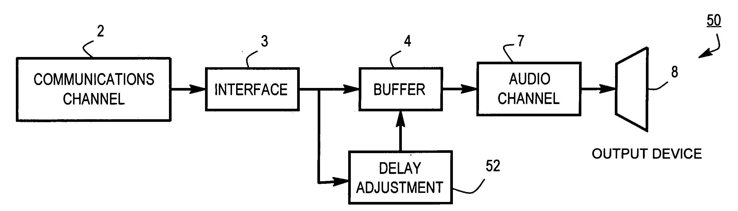
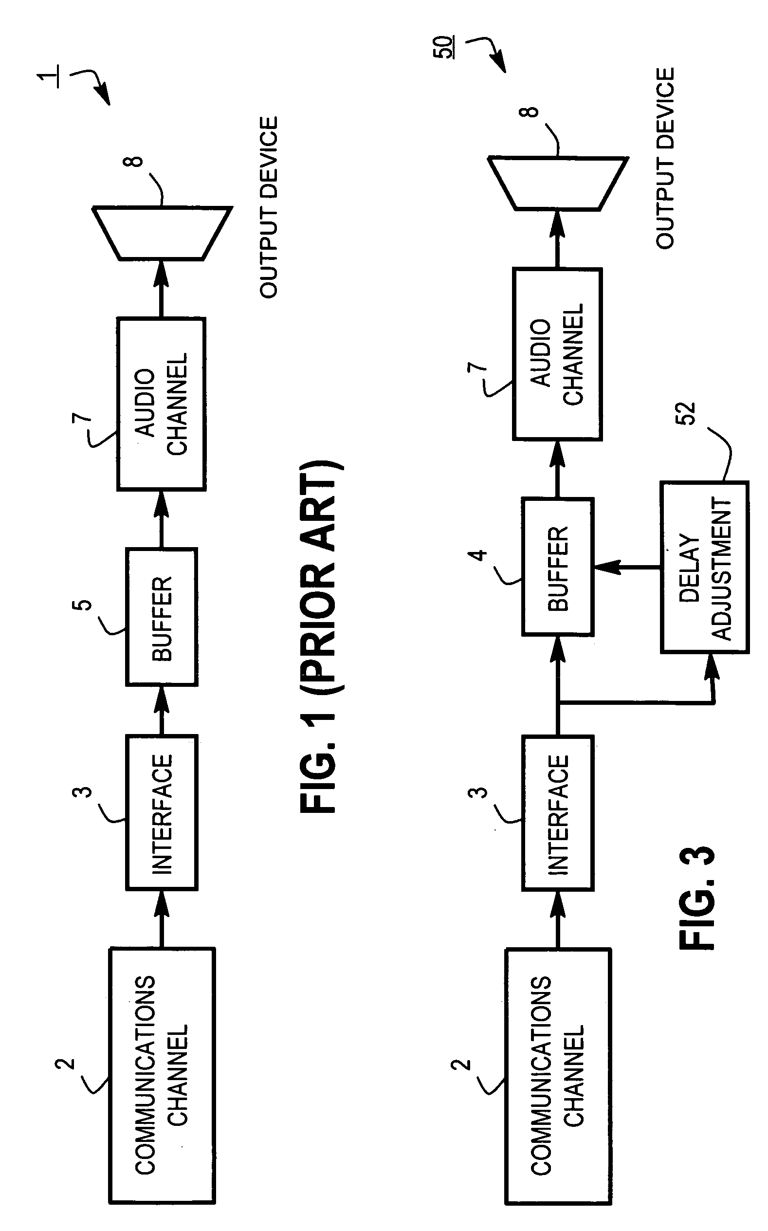
Controlling Jitter Buffer Delay.

[0045] In this section, we discuss certain concepts in connection with controlling jitter buffer delay. We begin with a simple statement. If neither transmitter, network nor receiver are losing or changing the order of audio, then one-way delay may only grow in time.

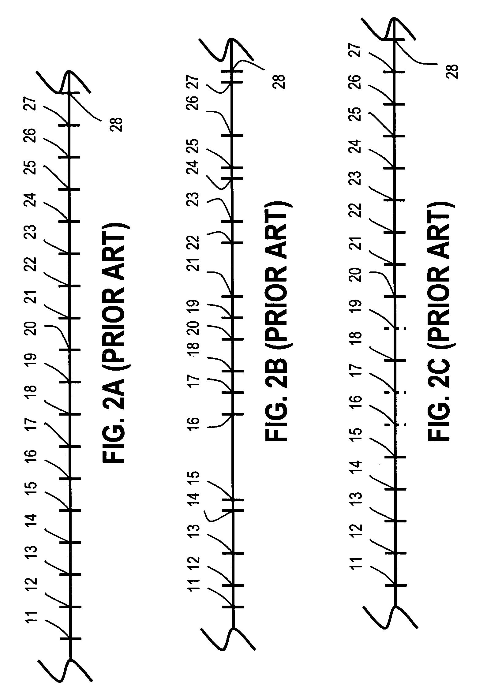
[0046] Indeed, if A0 and B0 are some points in a source audio (transmitter input), point B0 is after point A0; A1 and A0 are corresponding points in the receiver output audio and T(X) is the time of event X, then

T(B1)−T(A1)≧T(B0)−T(A0),

[0047] because all audio that filled time segment [T(A0), T(B0)] is now in segment [T(A1), T(B1)]. That means

T(B1)−T(B0)≧T(A1)−T(A0),

[0048] which proves the statement.

[0049] That is not absolutely true in the digital case because the transmitter and the receiver can have different timers. However, it is close to being true, at least if we are assuming that their clocks are synchronized, in order to simplify the analysis.

[0050] When the jitter buffer...


PUM


Abstract

Generally speaking, there are provided systematic techniques for increasing and decreasing jitter buffer delay. The disclosed techniques typically utilize various combinations of: evaluating received data over a specified interval, increasing a recommended buffer delay if the interval delay exceeds a first threshold and decreasing the recommended buffer delay if the interval delay is less than a second threshold, causing the recommended buffer delay to decrease over time until an underflow condition is identified, and/or increasing the recommended buffer delay in response to identifying the underflow condition.

Description

BACKGROUND OF THE INVENTION [0001] 1. Field of the Invention [0002] The present invention pertains to an audio receiver having an adaptive buffer delay, and is particularly applicable to a voice-over-IP (Internet Protocol), or VoIP, receiver, such as may be used for telephone communications over the Internet. [0003] 2. Description of the Related Art [0004] Recently, telephone communications over the Internet and VoIP within an office setting have become increasingly popular. The former has been primarily due to lower cost and the latter has been primarily due to better flexibility (including more seamless integration with the office's computer system) than earlier telephone systems could provide. [0005] A simple block diagram of the receiving portion of a conventional VoIP system is illustrated in FIG. 1. In FIG. 1, audio communications are received as packet-based digital data through a communications channel 2, which typically is the Internet or some other Internet protocol (IP) n...

Claims


Application Information

Patent Timeline
IPC IPC(8): H04L12/56H04L12/66
CPCH04J3/0632H04L12/6418H04L47/10H04L47/28H04L49/90H04L49/9031H04L2012/6489H04L49/9023
Inventor TALALAI, ALEXANDER
Owner PIVOT VOIP
Why Eureka
Try Eureka