Automatic time delay deviation estimation and compensation device for measurement and control antenna array

A technology of delay deviation and antenna array, which is applied in related application fields, can solve the problems of poor estimation accuracy, achieve the effect of adapting to low signal-to-noise ratio, improving the signal-to-noise ratio of composite signals, and high compensation accuracy

Pending Publication Date: 2021-11-02
NO 54 INST OF CHINA ELECTRONICS SCI & TECH GRP
View PDF0 Cites 0 Cited by
  • Summary
  • Abstract
  • Description
  • Claims
  • Application Information

AI Technical Summary

Problems solved by technology

The traditional time delay deviation adopts time-domain correlation estimation technology, which is only suitable for high signal-to-noise ratio, and the estimation accuracy is poor

Method used


Image

  • Automatic time delay deviation estimation and compensation device for measurement and control antenna array

Examples


Embodiment Construction

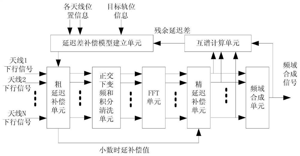
[0018] refer to figure 1 , an automatic delay deviation estimation and compensation device for a measurement and control antenna array, including a delay difference model establishment unit, a coarse delay compensation unit, an orthogonal down-conversion and integral cleaning unit, an FFT unit, a fine delay compensation unit, a frequency domain synthesis unit and Cross-spectrum calculation unit;

[0019] Delay difference model building unit: used to select any antenna from antenna 1 to antenna N as a reference antenna, and establish a delay prediction model from antenna 1 to antenna N according to the external input target orbit position information and the position coordinate information of each antenna, And make the difference with the reference antenna respectively to get the inter-station delay difference polynomial τ k (t), and correct the inter-station delay difference polynomial according to the residual delay difference and residual phase difference of the cross-spect...


PUM


Abstract

The invention discloses an automatic time delay deviation estimation and compensation device for a measurement and control antenna array, and the device carries out the preprocessing of down-conversion, filtering, integral cleaning and the like on a multi-antenna receiving signal, carries out the FFT of the preprocessed signal, builds a delay difference compensation model through the fitting of a frequency domain cross-spectrum signal, extracts the time delay deviation between multiple antennas, and compensates the integer sampling interval delay deviation and the decimal sampling interval delay deviation in the time domain and the frequency domain respectively. The method is suitable for time delay deviation alignment among signals received by multiple antennas under the condition of low signal-to-noise ratio, and has the advantages of high time delay deviation estimation and compensation precision and the like.

Description

technical field [0001] The present invention relates to reception antenna array signal synthesis technology in deep space measurement and control communication, distributed radar transceiver coherent synthesis technology, interferometric data processing technology, etc., and is especially suitable for efficient synthesis and real-time Synthesis and other related applications. Background technique [0002] In the deep space measurement and control communication system, due to the distance between the deep space spacecraft target and the earth station, ranging from tens of millions to hundreds of millions of kilometers, the received signal strength of the existing measurement and control communication equipment is very weak. The receiving antenna array is an effective means to improve the SNR of the received signal, but to achieve antenna array synthesis, it is first necessary to correct and align the received signals of each antenna for delay deviation, phase deviation, and f...

Claims


Application Information

Patent Timeline
IPC IPC(8): G01R29/10G01R29/08G01R23/16G01R35/00
CPCG01R29/10G01R29/0892G01R23/16G01R35/005G01R35/007
Inventor 刘友永孟玮耿虎军
Owner NO 54 INST OF CHINA ELECTRONICS SCI & TECH GRP
Why Eureka
Try Eureka