Heat pump system

a heat pump and heat engine technology, applied in the field of heat pump systems, can solve the problems of low efficiency, low efficiency, and high cost of heat pump components, and achieve the effects of increasing the efficiency of the heat pump system, reducing friction, and improving the operation efficiency of the heat engin

Inactive Publication Date: 2006-06-08
SOLOMON FRED D
View PDF13 Cites 9 Cited by
  • Summary
  • Abstract
  • Description
  • Claims
  • Application Information

AI Technical Summary

Benefits of technology

[0012] Another object of the present invention is to provide a heat pump system wherein the heat engine of the power section and the compressor of the compressor section constitute a combined or consolidated unit. Another object of the invention is to provide such a combined heat engine and compressor assembly which does not require a fluid interconnection between the engine and the compressor. Still another object of the present invention is to provide such a combined heat engine and compressor assembly wherein the pistons of the heat engine and the compressor are mechanically interconnected. Yet another object of the present invention is to provide such a combined heat engine and compressor assembly which prevents migration of working fluid from the high pressure side to the low pressure side by employing two spaced rolling diaphragm seals having pressurized water therebetween, both the diaphragms and the water combining to constitute an effective barrier to refrigerant migration.
[0013] A further object of the present invention is to provide a heat pump system wherein a unique valve controls the ingress and egress of fluids into the chamber housing the heat engine piston. Another object of the invention is to provide such a valve which provides transition between the power and exhaust strokes by smooth, positive motion which prevents any bleedover when the piston power chamber is shifted between exhaust and high pressure operating conditions. Still another object of the present invention is to provide such a valve which does not require either electrical or mechanical shifting mechanisms to effect operation of the valve.
[0015] Still a further object of the present invention is to provide a heat pump system wherein kinetic energy from the exhaust at the end of the power stroke of the heat engine piston is employed to assist the power stroke. Another object of the invention is to employ the exhaust from the heat engine to operate a turbine driving a pump which creates a vacuum condition on the back side of the heat engine piston to assist in the power stroke of the heat engine piston. A further object of the present invention is to provide a turbo impeller and pump arrangement which may be energized solely by vapor exiting the heat engine chamber or which can be supplemented by an electric motor or solar powered motor to further increase operating efficiency of the heat engine.
[0016] Yet a further object of the invention is to provide such a heat pump system wherein all moving parts and sealing areas can be constructed of relatively low-cost ceramic materials due to the fact that the entire system operates at relatively low temperatures. A further object of the present invention is provide such a heat pump system wherein the ceramic materials used for the moving parts and sealing areas increase efficiency of the heat pump system by providing for fluid-tight but low friction sliding engagement. A further object of the invention is to provide such a heat pump system which may employ a working fluid in the heat engine section which requires substantially less heat per hour for conversion to vapor, thus representing a substantial increase in overall efficiency of the heat pump system.
[0018] Yet still a further object of the invention is to provide a heat pump system which can readily employ a variety of heat exchangers and other design features which permit further optimizing the overall efficiency of both the heat engine system and the compressor system. A further object of the invention is provide a heat pump system wherein the heat exchanger is a triple-tube type and is used to heat water such as that contained in a swimming pool, hot water heater or the like. A further object of the invention is provide a heat pump system wherein the refrigerant from the compressor and the working fluid from the heat engine are directed to the triple-tube heat exchanger. A further object of the invention is provide a heat pump system wherein heat from the refrigerant and from the working fluid is transferred to water from the swimming pool, hot water heater or the like.

Problems solved by technology

However, due to the relatively advanced age and state of development of this technology, only minor improvements in operation and efficiency have been achieved through research and development efforts of this nature in recent years.
Heat driven heat pumps of these types have not achieved commercial acceptance and recognition for a number of reasons.
In general, devices of this nature tend to be highly complex systems having component elements which are both sophisticated and expensive.
With the technical limitations on working fluid and component improvements and the lack of commercial acceptance of heat driven heat pump systems, these systems have remained in essentially the same state of technological development for a substantial number of years.
Heat driven heat pumps employing heat engines and conventional working fluids have been developed but typically suffer from a number of disadvantages.
When this fluid is discharged into a condenser there is a loss of a significant amount of kinetic and thermal energy, thereby rendering the overall system highly inefficient.
Another problem area in such heat driven heat pumps is that it is desirable to combine the heat engine and compressor within a single housing having a piston rod connecting the heat engine piston and the compressor piston.
Under these circumstances, it is a common problem to have the higher pressure working fluid eventually migrate through any seals into the lower pressure working fluid and thereby adversely alter the operating characteristics of the lower pressure working fluid.
A further difficulty in the design of heat engines is in providing a valve to effect shifting between high vapor pressure power stroke and exhaust stroke.
When a conventional valve shifts, it allows vapor to blast into the cylinder so rapidly that it induces the entire heat pump to vibrate or shake violently, thereby shortening the life of the heat engine and being otherwise objectionable.
Efforts to slow the valve shift motion have been unsuccessful because vapor will leak by the valve when it slowly passes from high vapor pressure position to the exhaust position.
Another notorious problem with heat engines is in effecting start-up if the unit has not been running and is cold.
Since there is a limited amount of working fluid in the heat generator it can run low on working fluid before the power chamber of the heat engine reaches operating temperature.
This causes overheating of the heat generator and possible scorching of the working fluid, thereby requiring major servicing before the heat pump can resume normal operation.
As a result of various of the above factors or combinations thereof, heat driven heat pump systems have not achieved any extent of commercial acceptance.

Method used


Image

  • Heat pump system
  • Heat pump system
  • Heat pump system

Examples


Embodiment Construction

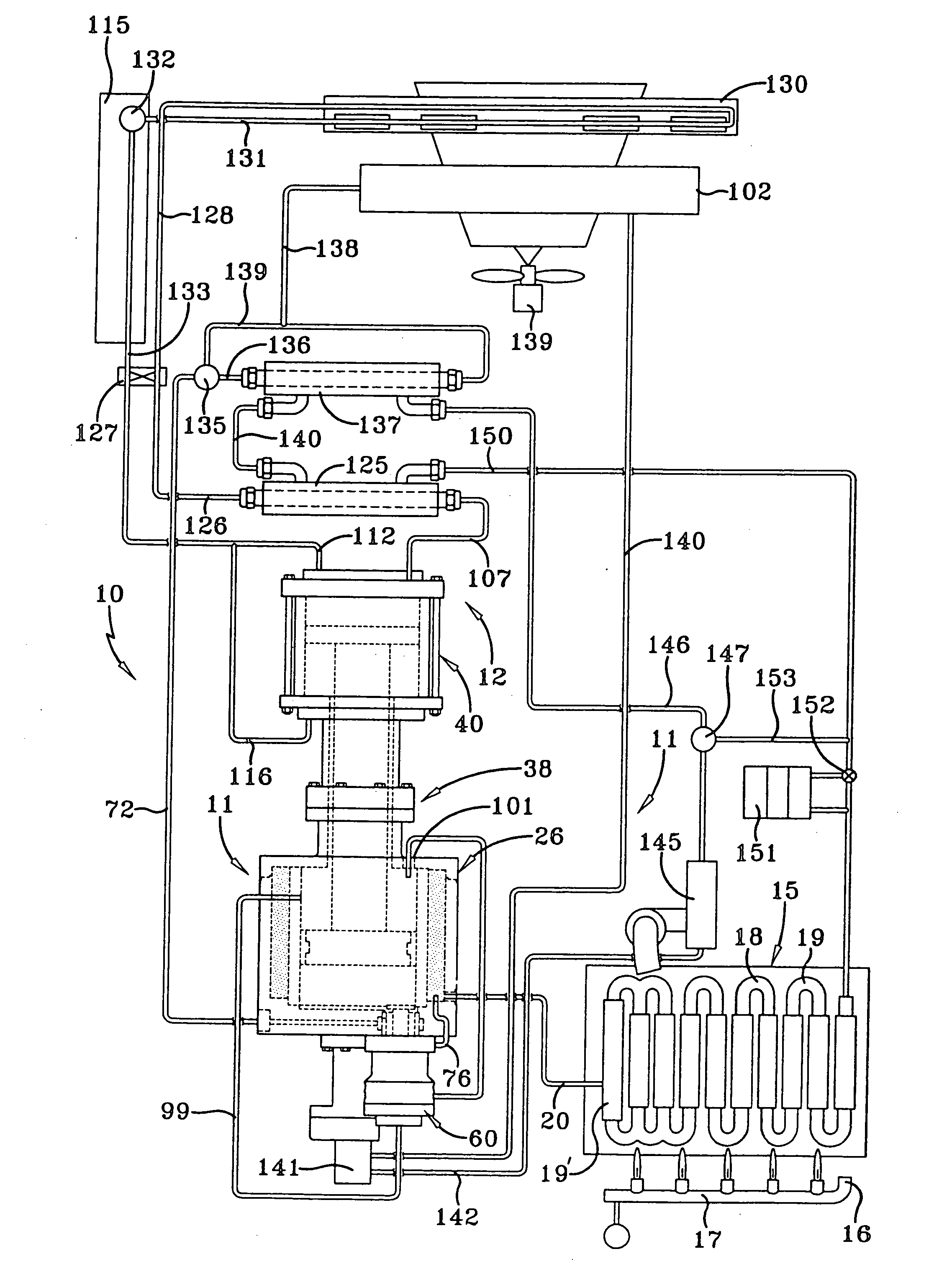
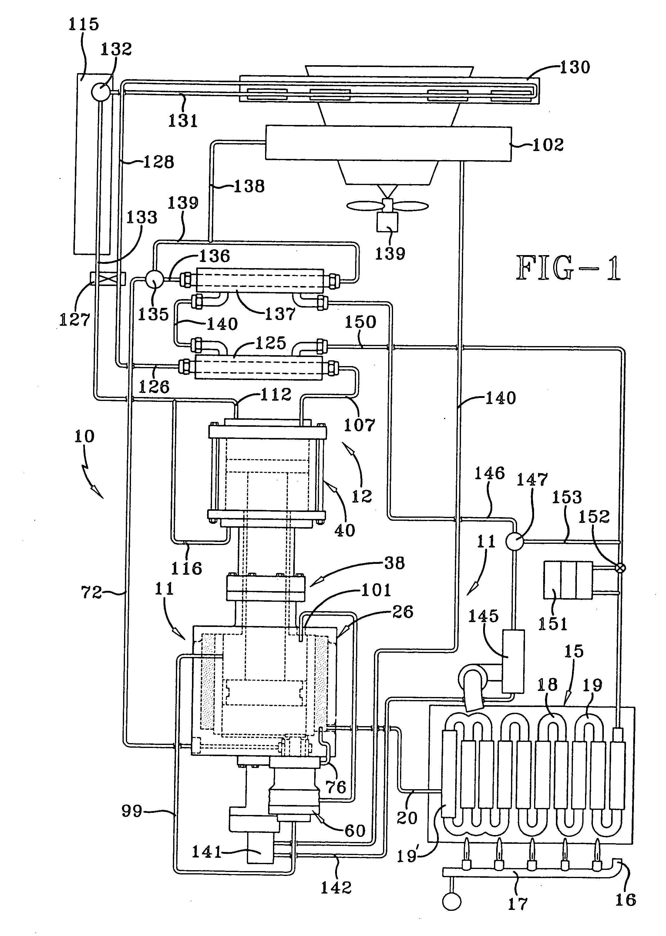
[0028] An exemplary heat pump system embodying the concepts of the present invention is generally indicated by the numeral 10 in FIG. 1 of the drawings. While the exemplary heat pump system 10 shown and described herein is particularly applicable to a three-ton unit of a type which might be employed for residential purposes, larger or smaller units can be employed depending upon the requirements and the invention may be readily adapted to vehicles or other applications, particularly in instances where excess heat may be available.

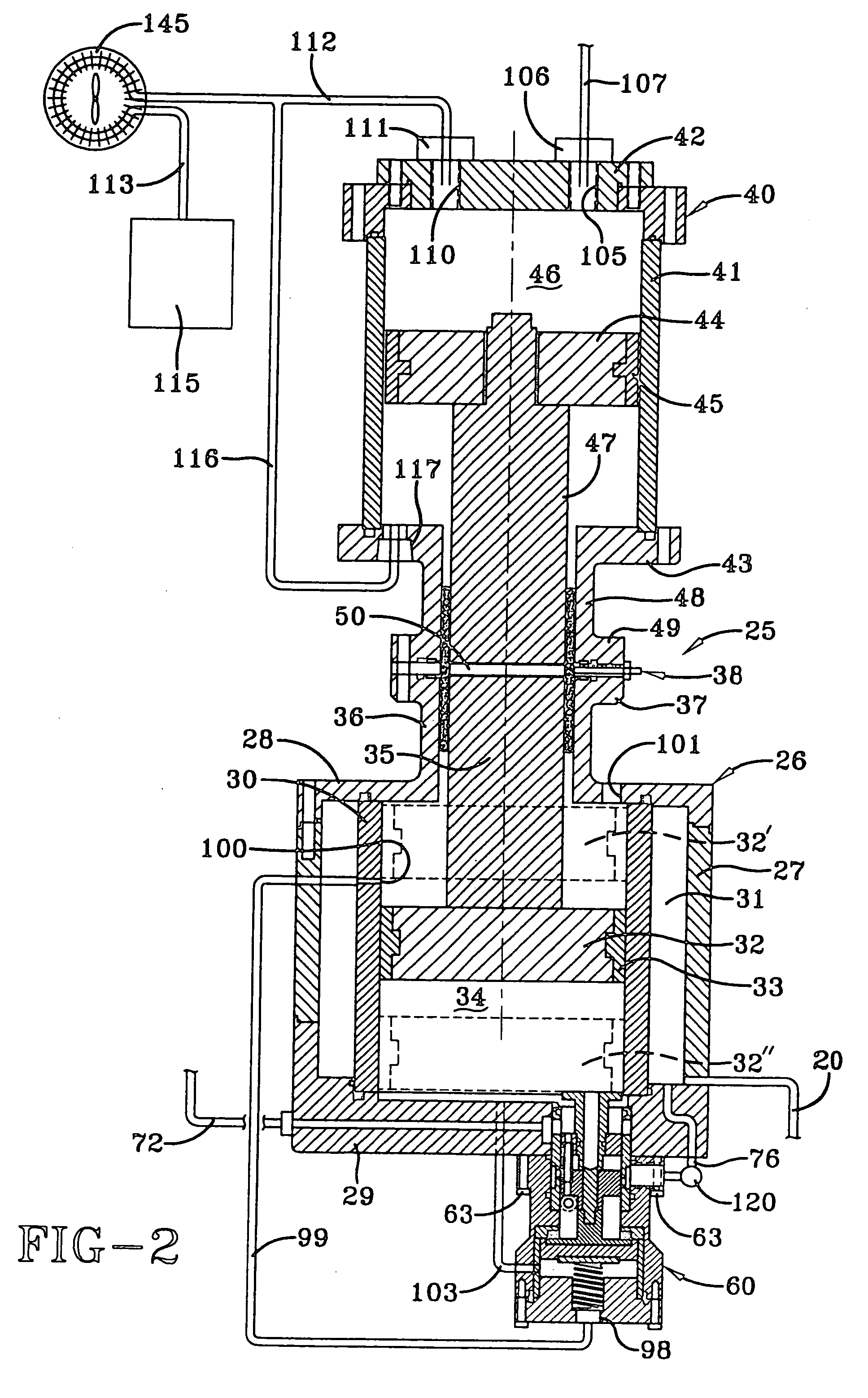
[0029] The heat pump system 10 has a power section, generally indicated by the numeral 11, which drives and otherwise interrelates with a compressor section, generally indicated by the numeral 12. As will be appreciated from the following description, the power section 11 employs a Rankin cycle, and the compressor section 12 employs a vapor compression cycle. As a result, differing working fluids are employed in the power section 11 and the compressor sect...


PUM


Abstract

A heat pump system (10) including a heat generator (15), a heat engine (26) supplied with heat engine working fluid (18) by the heat generator (15) having a heat engine cylinder chamber (34), a heat engine piston (32), and a heat engine piston rod (35), a preheating chamber (31) employing the heat engine working fluid (18) to heat the heat engine cylinder chamber (34), a compressor (40) driven by the heat engine (26) employing compressor working fluid having a compressor cylinder chamber (46), a compressor piston (44), and a compressor piston rod (47), a spacer (50) separating and joining the heat engine piston rod (35) and the compressor piston rod (47), a sealing assembly (38) associated with the spacer (50) separating the heat engine working fluid (18) and the compressor working fluid, and a valve assembly (60) communicating with the heat engine cylinder chamber (34) and controlling the ingress and egress of heat engine working fluid (18) to the heat engine (26).

Description

CROSS REFERENCE TO RELATED APPLICATION [0001] This application is a divisional of U.S. Ser. No. 10 / 829,515, filed on Apr. 22, 2004, which was a divisional of U.S. Ser. No. 10 / 447,369 filed May 29, 2003, now U.S. Pat. No. 6,739,139.TECHNICAL FIELD [0002] In general, the present invention relates to a heat pump system capable of providing heating and cooling requirements for residential and other applications. More particularly, the invention relates to a heat pump system providing such heating and cooling by employing a heat engine. More specifically, the invention relates to a heat pump system in which such a heat engine interacts with the remainder of the system in such a manner as to provide greatly improved efficiency and other performance characteristics. BACKGROUND ART [0003] Heat pumps have long been known and employed in the heating, ventilating, and air conditioning industry. A significant reason for the extensive use and focus of attention on heat pump systems is that the s...

Claims


Application Information

Patent Timeline
Patent Type & Authority Applications(United States)
IPC IPC(8): F25B27/00F02B71/00F02G5/00F25B13/00F25B40/04
CPCF02B71/00F02G5/00F25B13/00Y02B30/52F25B40/04Y02T10/166F25B27/00Y02T10/12E04H4/129
Inventor SOLOMON, FRED D.
Owner SOLOMON FRED D
Why Eureka
Try Eureka