Surface light source control device

Inactive Publication Date: 2006-06-29
JAPAN DISPLAY CENT INC
View PDF3 Cites 31 Cited by
  • Summary
  • Abstract
  • Description
  • Claims
  • Application Information

AI Technical Summary

Benefits of technology

[0009] An object of the embodiments of the present invention is to provide a surface light source control device which can set power supply voltages to be applied to a p

Problems solved by technology

Moreover, there is a problem in that an excess current flows into each LED array to cause reductions in service life of each LED.
However, the foregoing conventional liquid crystal display device needs adjustment operations for the adjustment resistors and requ

Method used


Image

  • Surface light source control device
  • Surface light source control device
  • Surface light source control device

Examples


Embodiment Construction

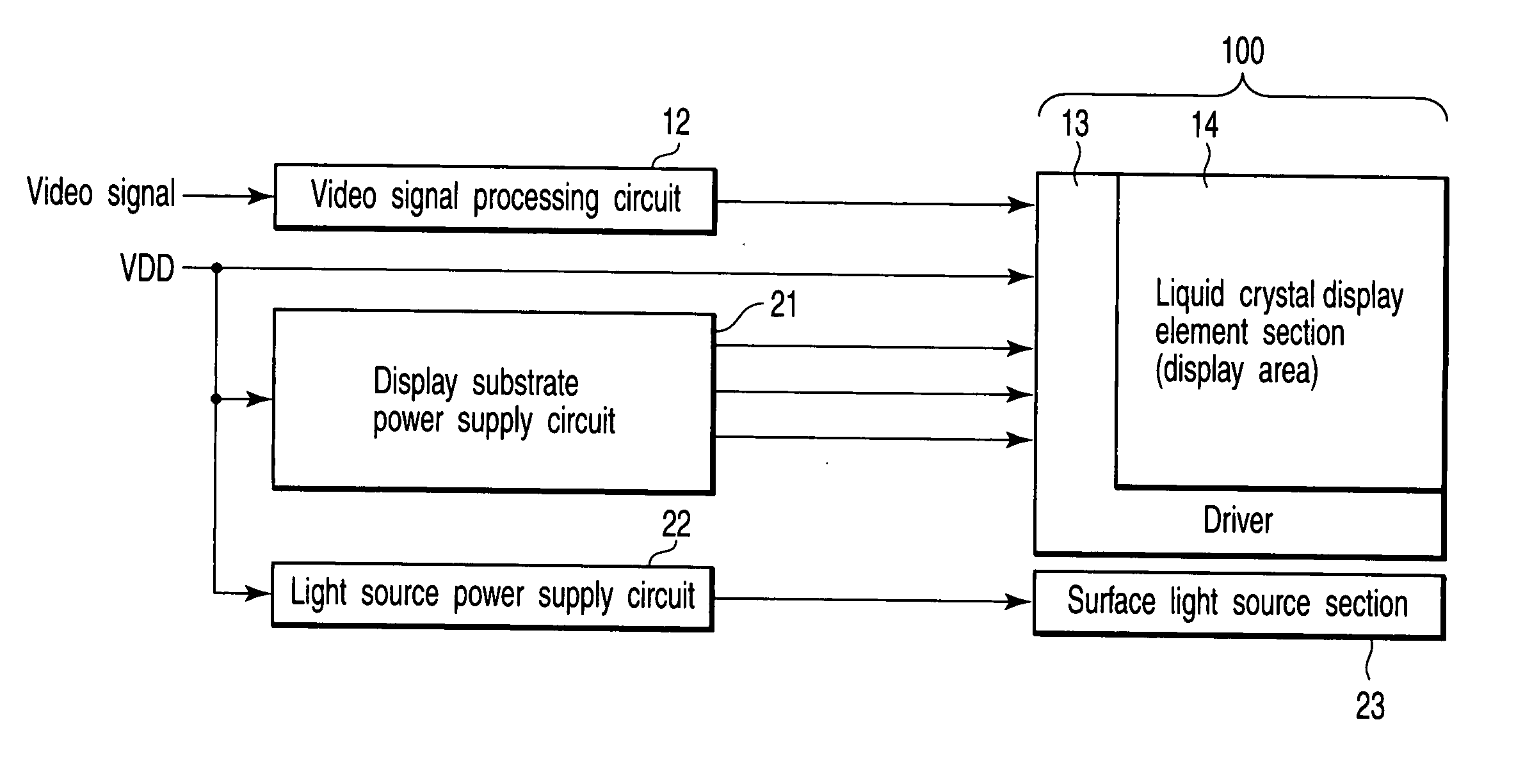
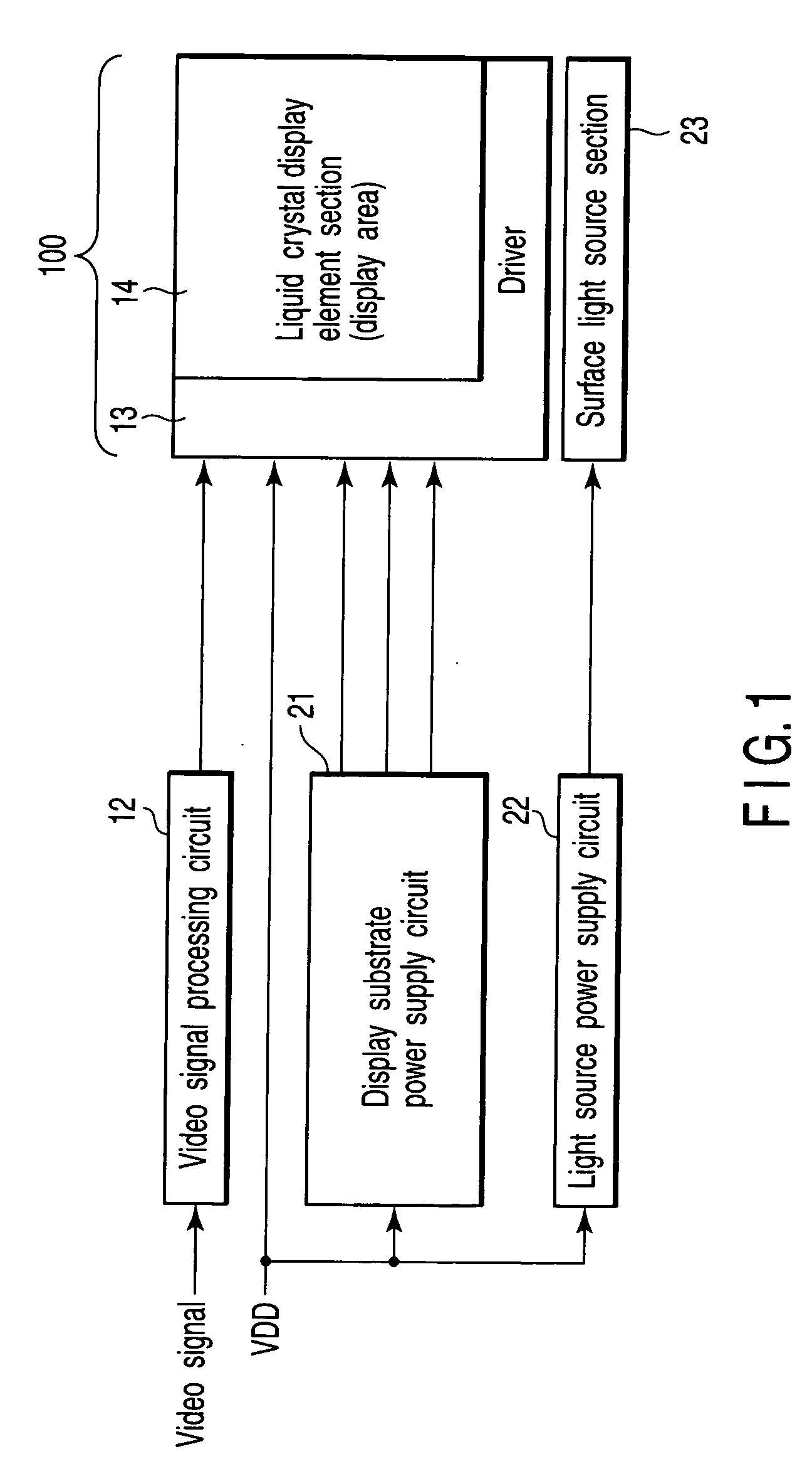
[0017] Hereinafter, embodiments of the present invention will be described in detail with reference to the drawings. FIG. 1 shows a schematic configuration of a liquid crystal display device. In a liquid crystal display element section (also referred to as a display area) 14 formed on a transparent glass substrate included in a liquid crystal panel 100, pixels including thin film transistors, pixel electrodes, auxiliary capacitor and the like are two-dimensionally arrayed. And a plurality of signal lines are formed in vertical directions and a plurality of scanning lines are formed in horizontal directions and the pixels are respectively arranged in the vicinity of points at which the plurality of signal lines and scanning lines are intersected. Furthermore, a driver 13 including a scanning line drive circuit and a signal line drive circuit is arranged around the display element section 14.

[0018] A pixel signal from a video signal processing circuit 12 is supplied to the signal lin...


PUM


Abstract

A surface light source control device has a plane light source control circuit for setting a current amount to a plurality of diode arrays. The light source control circuit comprises a constant current circuit for holding currents respectively flowing in the plurality of diode arrays constant at the same current value; and a power supply voltage control loop for selecting a notable diode array with a minimum reference voltage, among reference voltages appearing at each terminal of the plurality of diode arrays, appeared thereon to select the minimum reference voltage by a voltage selection circuit and adjusting a common power supply voltage so that the reference voltage becomes a prescribed value.

Description

CROSS-REFERENCE TO RELATED APPLICATIONS [0001] This application is based upon and-claims the benefit of priority from prior Japanese Patent Application No. 2004-374517, filed Dec. 24, 2004, the entire contents of which are incorporated herein by reference. BACKGROUND OF THE INVENTION [0002] 1. Field of the Invention [0003] The present invention relates to a surface light source control device usable for a liquid crystal display device, and more particularly relates to such a surface light source control device for making a power supply voltage, which is applied to a plurality of arrays of light emitting diodes composing a plane light source section, low in power consumption on the plurality of light emitting diode arrays. [0004] 2. Description of the Related Art [0005] Some conventional liquid crystal display devices adopt plane light source sections using light emitting diodes as backlights. Each of these light source sections has a light emitting diode (LED) light source equipped ...

Claims


Application Information

Patent Timeline
IPC IPC(8): G09G3/36H01L33/00
CPCG09G3/3406G09G2320/0233
Inventor TSUCHIYA, KENSHI
Owner JAPAN DISPLAY CENT INC
Why Eureka
Try Eureka