
Door or wing for electrical household appliances

a technology for electrical household appliances and doors, applied in the field of doors or wings for electrical household appliances, can solve the problems of most complex and time-consuming, and hence cost-intensive, and achieve the effect of reducing difficulty and cost and good operating efficiency

Active Publication Date: 2015-07-14
NUOVA STAR
View PDF12 Cites 6 Cited by
  • Summary
  • Abstract
  • Description
  • Claims
  • Application Information

AI Technical Summary

Benefits of technology

This design reduces assembly complexity and costs while maintaining efficient door operation, ensuring safety compliance and operational efficiency by simplifying the assembly process and integrating limit stops into the link rod, allowing for effective door movement and stable positions without requiring elastic elements in all hinges.

Problems solved by technology

One of the most complex and time-consuming, and hence cost-intensive, steps in the assembly of a hinge is that of inserting into one of its components the elastic elements described above which must be mounted in a preloaded condition if they are to operate effectively.

Method used


Image

  • Door or wing for electrical household appliances
  • Door or wing for electrical household appliances
  • Door or wing for electrical household appliances

Examples


Embodiment Construction

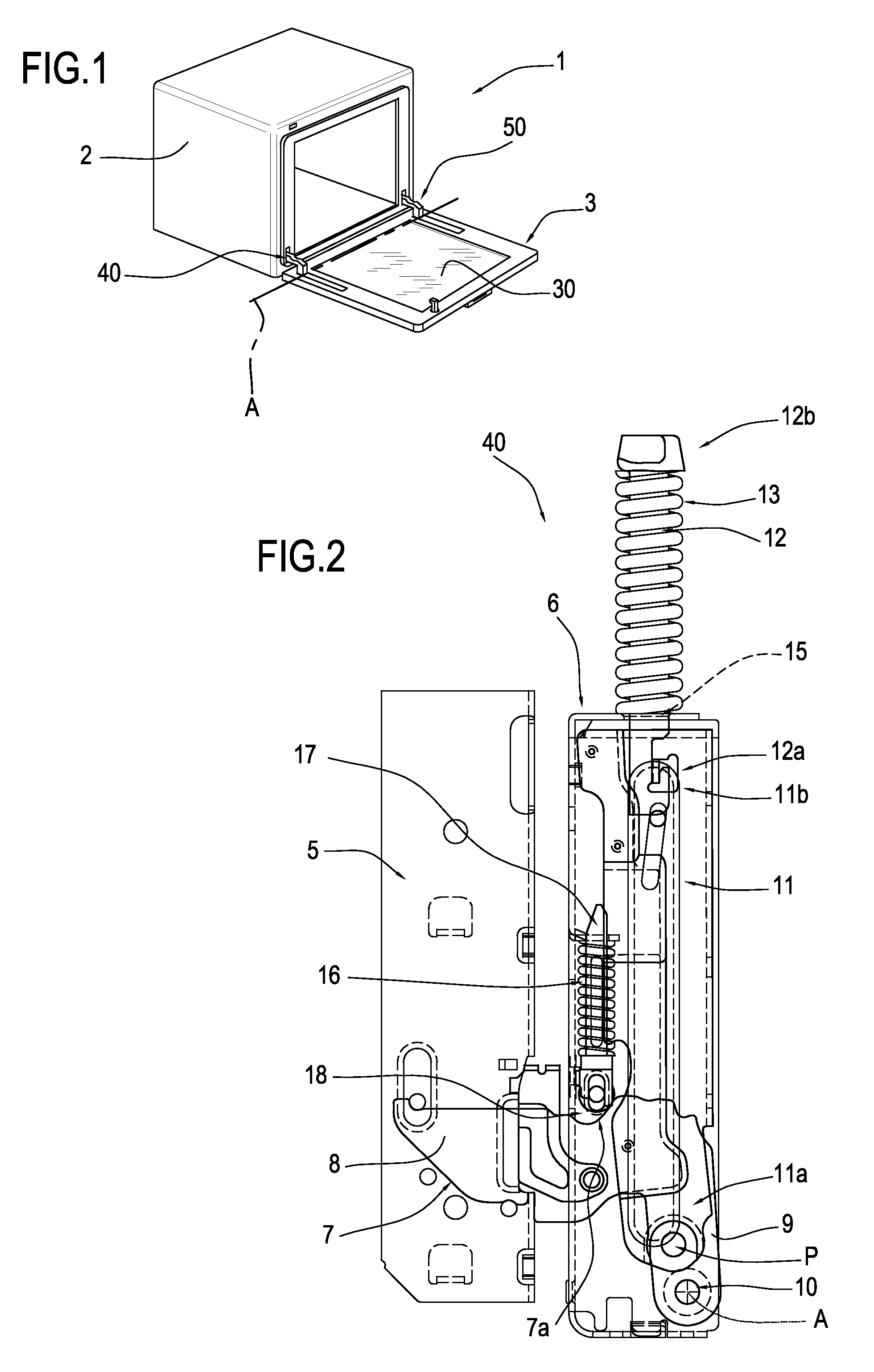
[0019]The numeral 1 in FIG. 1 denotes in its entirety an oven comprising a frame 2 to which a door 3 is connected.

[0020]The door 3 comprises a pivoting element 30 and two hinges 40, 50 by which the pivoting element 30 can be tilted about a horizontal axis A.

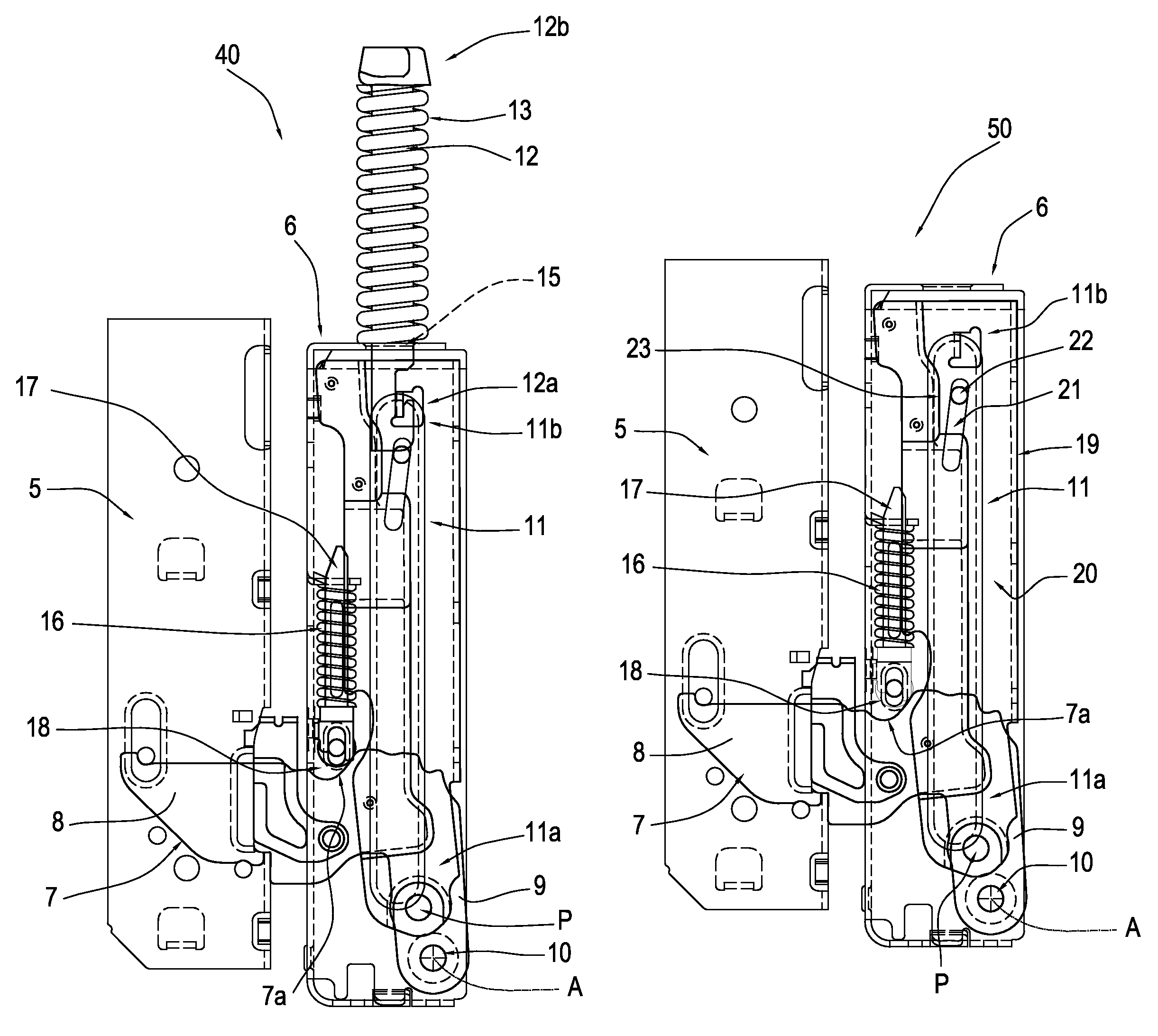
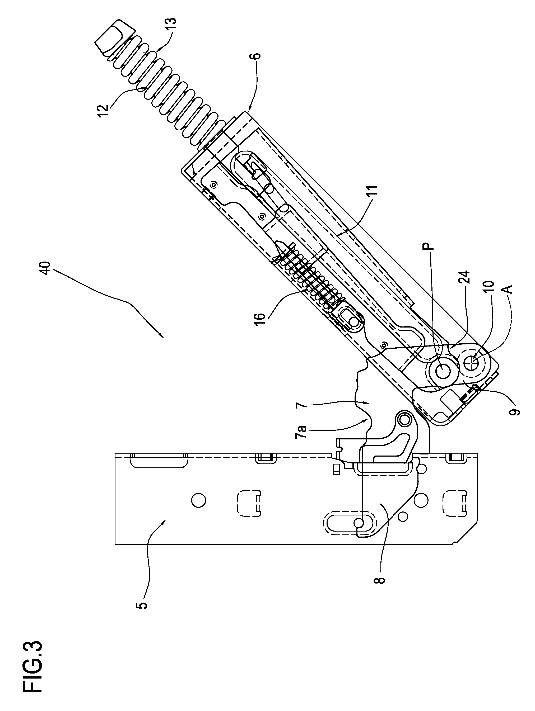
[0021]With reference to FIGS. 2 to 4, the hinge 40, of substantially known type, comprises a first box-shaped member 5 fixed to the frame 2 of the oven 1, and a second member 6, also box-shaped, fixed to the door 3. The first and second box-shaped members 5, 6 are kinematically connected by a connecting lever 7.

[0022]The connecting lever 7 comprises a first arm 8, designed to be rigidly connected to the first box-shaped member 5, and a second arm 9 connected to the second box-shaped member 6.

[0023]For connecting the second arm 9 and the second box-shaped member 6 to each other, the hinge 40 comprises a first pin 10 passing through a respective hole made in the end of the second arm 9 itself and being coaxial with the axis A.

[0024...


PUM


Abstract

A door or wing for electrical household appliances comprises a pivoting element (30) and two hinges (40, 50) mounted along one perimetric side of the pivoting element (30) to join the pivoting element (30) to a frame (2) and make it movable relative to the latter between a closed position and an open position, each of the two hinges (40, 50) comprising a first member and a second, box-shaped member and a lever for connecting the first and second members.

Description

[0001]This application claims priority to Italian Patent Application BO2009A000547 filed Aug. 13, 2009, the entirety of which is incorporated by reference herein.BACKGROUND OF THE INVENTION[0002]This invention relates to a door or wing for electrical household appliances.[0003]More specifically, this invention has for its subject-matter a door or wing connected to the respective mounting structure of an electrical household appliance such as an oven.[0004]This specification describes this invention with reference to an oven purely by way of example and without restricting the scope of the inventive concept.[0005]Prior art doors or wings comprise two hinges used to connect them to the structure of an oven or other electrical household appliance.[0006]The hinges normally consist of two separate parts kinematically linked to each other, either directly or through an interposed lever.[0007]More specifically, the first part is fixed to the oven structure on one side of the oven opening, ...

Claims


Application Information

Patent Timeline
Patent Type & Authority Patents(United States)
IPC IPC(8): E05F1/12F24C15/02
CPCE05F1/1261F24C15/023E05Y2900/308E05Y2800/22
Inventor VANINI, ANGELO
Owner NUOVA STAR
Learn More